
Physical quantity sensor and electronic apparatus

Active Publication Date: 2013-08-01
SEIKO EPSON CORP
View PDF13 Cites 32 Cited by
  • Summary
  • Abstract
  • Description
  • Claims
  • Application Information

AI Technical Summary

Benefits of technology

This patent is about a new physical quantity sensor and an electronic apparatus that includes it. The sensor has several advantages such as high reliability and ease of manufacturing. It prevents damage to the sensor when subjected to large acceleration. The sensor is made up of an oscillating member with a protrusion that prevents collisions with the substrate. By designing the gap between the oscillating member and the protrusion to be constant, the sensor is made more efficiently using a single etching process. The electronic apparatus made using this sensor simplifies manufacturing processes and achieves high reliability.

Problems solved by technology

However, in the physical quantity sensor disclosed in JP-A-2008-529001, the stopper has to be formed by depositing and patterning a predetermined material on the proof mass, thereby causing complication of manufacturing processes thereof.

Method used


Image

  • Physical quantity sensor and electronic apparatus
  • Physical quantity sensor and electronic apparatus
  • Physical quantity sensor and electronic apparatus

Examples


first modification example

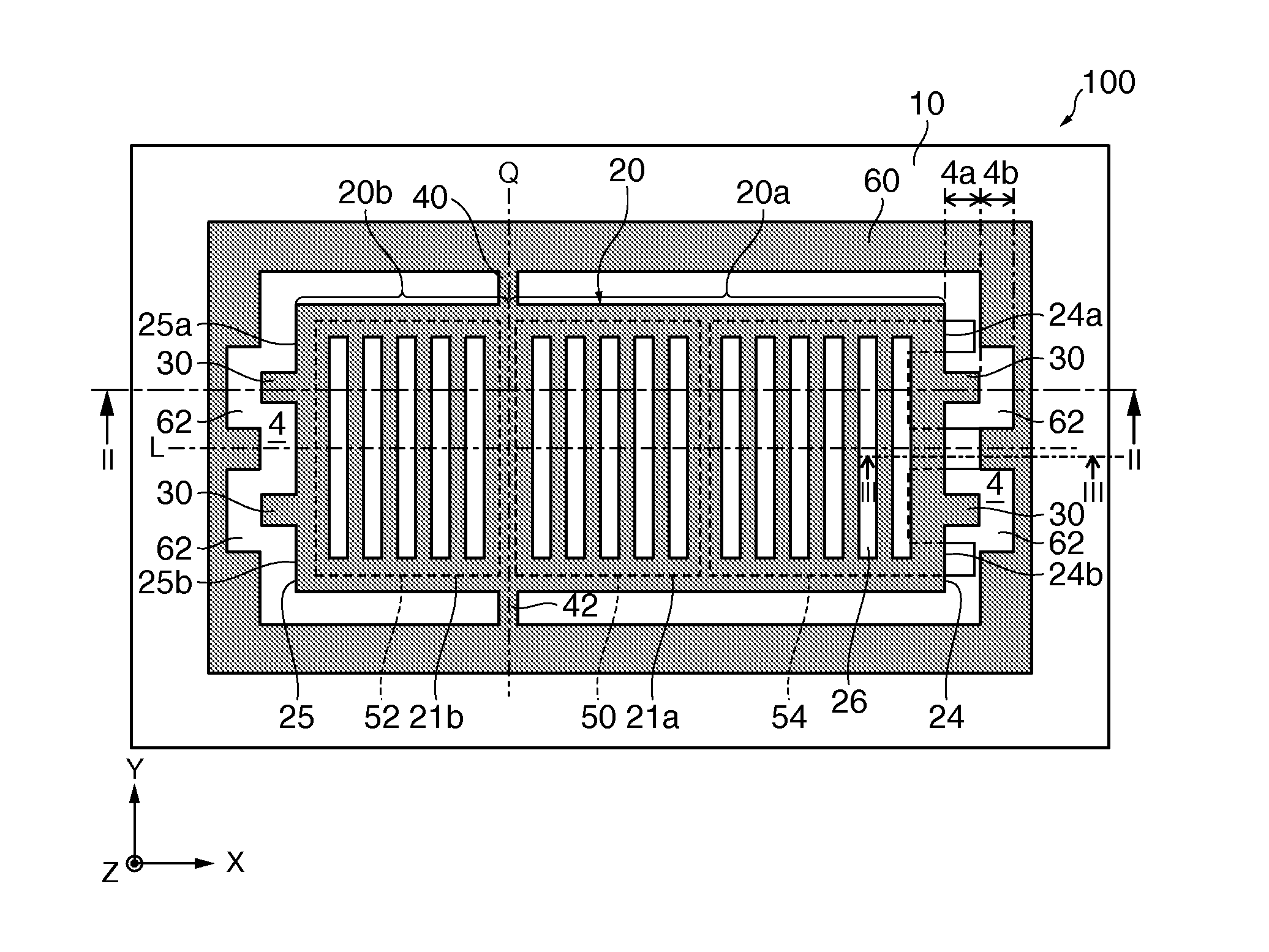
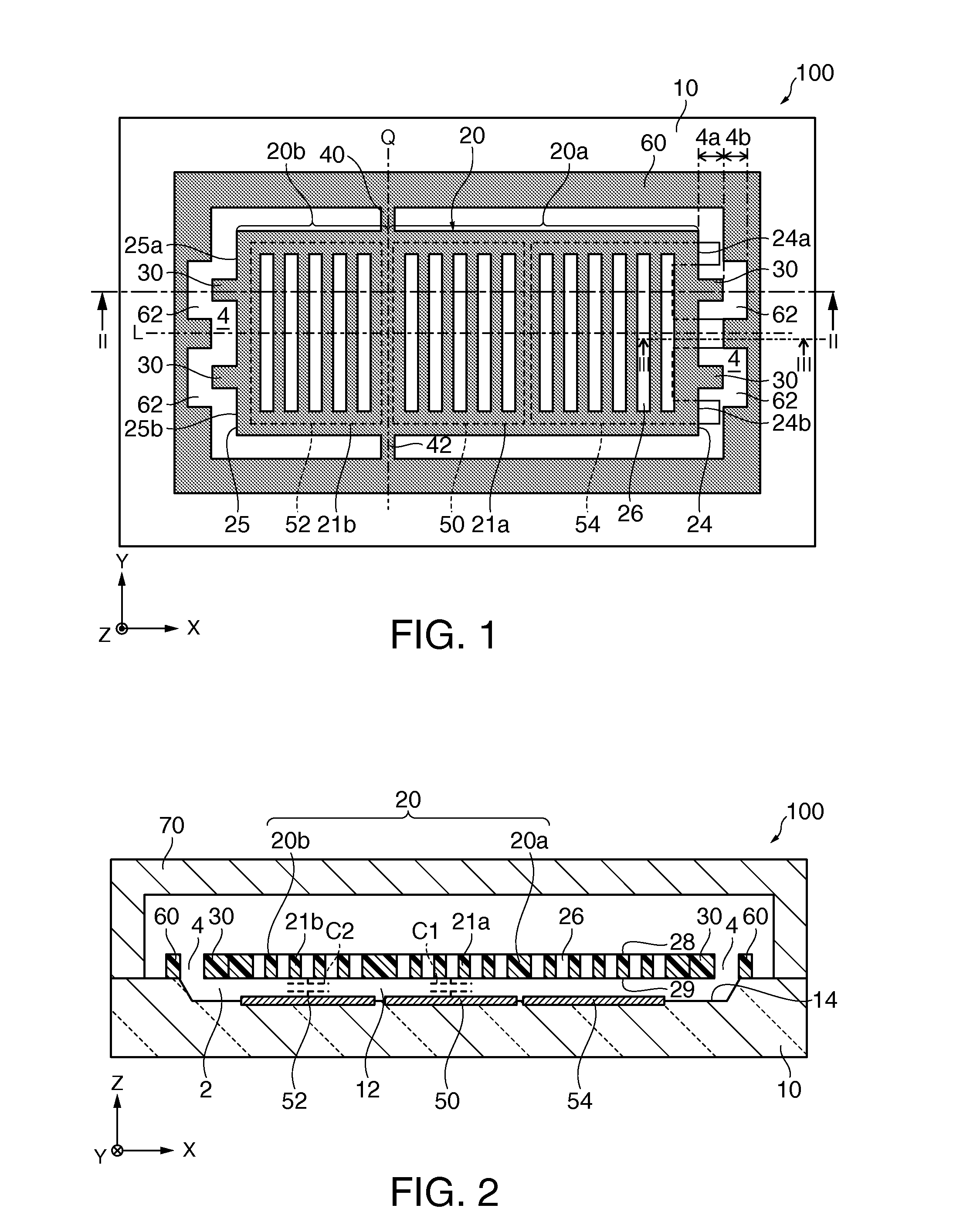
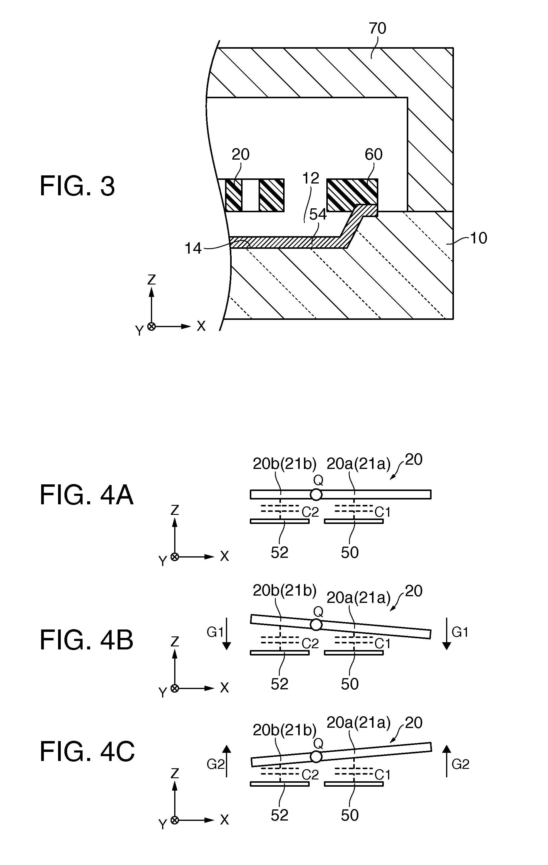
[0103]First, a physical quantity sensor according to a first modification example of this exemplary embodiment will be described with reference to the accompanying drawings. FIG. 9 is a plan view schematically illustrating a physical quantity sensor 200 according to the first modification example of this exemplary embodiment. In the physical quantity sensor 200 according to the first modification example of this exemplary embodiment, elements having the same functions as the constituent elements of the physical quantity sensor 100 according to this exemplary embodiment will be referenced by the same reference numerals and detailed description thereof will not be repeated.

[0104]In the example of the physical quantity sensor 100, as shown in FIG. 1, the protrusions 30 have a rectangular planar shape. On the contrary, in the physical quantity sensor 200, the protrusions 30 have a planar shape having a sharp-pointed tip. In the example shown in FIG. 9, the planar shape of the protrusion...

second modification example

[0106]A physical quantity sensor according to a second modification example of this exemplary embodiment will be described below with reference to the accompanying drawings.

[0107]FIG. 10 is a plan view schematically illustrating a physical quantity sensor 300 according to the second modification example of this exemplary embodiment. In the physical quantity sensor 300 according to the second modification example of this exemplary embodiment, elements having the same functions as the constituent elements of the physical quantity sensor 100 according to this exemplary embodiment will be referenced by the same reference numerals and detailed description thereof will not be repeated.

[0108]In the example of the physical quantity sensor 100, as shown in FIG. 1, the protrusions 30 have a rectangular planar shape. On the contrary, in the physical quantity sensor 300, the protrusions 30 have a planar shape having an arc-like tip. In the example shown in FIG. 10, the planar shape of the protr...


PUM


Abstract

A physical quantity sensor includes a substrate, an oscillating member that is disposed over the substrate, support portions that support the oscillating member and that are disposed along a first axis, and detection electrodes that are disposed on the substrate so as to oppose the oscillating member. The oscillating member has a pair of side faces intersecting a second axis perpendicular to the first axis in a plane, and a protrusion is formed on at least one of the pair of side faces.

Description

BACKGROUND[0001]1. Technical Field[0002]The present invention relates to a physical quantity sensor and an electronic apparatus.[0003]2. Related Art[0004]Recently, physical quantity sensors such as inertial sensors have been developed which detect a physical quantity, for example, using silicon MEMS (Micro Electro Mechanical System) techniques.[0005]For example, JP-A-2008-529001 discloses a seesaw physical quantity sensor that detects acceleration in a Z axis direction using an oscillating motion (seesaw oscillation). The physical quantity sensor disclosed in JP-A-2008-529001 includes a conductive plate and a proof mass having first and second regions which are different in mass from each other. The proof mass oscillates around an oscillation axis, which partitions the first and second regions, depending on the acceleration in the Z axis direction. The physical quantity sensor disclosed in JP-A-2008-529001 detects the acceleration on the basis of a variation in capacitance between t...

Claims


Application Information

Patent Timeline
IPC IPC(8): G01P15/02
CPCG01P15/02G01P15/0802G01P2015/0871G01P2015/0831G01P15/125
Inventor YODA, MITSUHIRO
Owner SEIKO EPSON CORP
Learn More