
Motion compensating catheter device

a catheter device and motion compensation technology, applied in the field of catheter devices, can solve the problems of not providing sufficient speed to compensate for the motion of the beating heart, the current catheter technology does not allow clinicians to interact with the beating heart tissue, and the traditional surgical procedure is very invasive, so as to improve the accuracy of the tip position and improve the accuracy of the tip for

Inactive Publication Date: 2013-07-25
PRESIDENT & FELLOWS OF HARVARD COLLEGE
View PDF17 Cites 42 Cited by
  • Summary
  • Abstract
  • Description
  • Claims
  • Application Information

AI Technical Summary

Benefits of technology

This patent describes a catheter system that uses motion compensation techniques to minimize injury during surgical procedures involving moving target areas. The system controls an actuator at the base of the catheter to drive a guide-wire inside a flexible catheter sheath to follow the motion of the target tissue. The system can use real-time imaging and image processing algorithms to track the catheter-tissue relationship and control the motion of the guide-wire tip, allowing for accurate tracking of the tissue motion. The catheter can provide more complex movements and compensation for friction and backlash to improve tip position and force accuracy. Overall, this invention provides a more efficient and safe tool for surgical procedures involving moving target areas.

Problems solved by technology

Traditional surgical procedures are very invasive involving large incisions and the displacement of the soft tissue around the organ or area to be operated on.
Nonetheless, current catheter technologies do not allow clinicians to interact with beating heart tissue in order to order to perform procedures that require open heart surgery.
However, these systems do not provide sufficient speeds to compensate for the motion of the beating heart.
These factors result in position hysteresis and significant tip trajectory errors.

Method used


Image

  • Motion compensating catheter device
  • Motion compensating catheter device
  • Motion compensating catheter device

Examples


Embodiment Construction

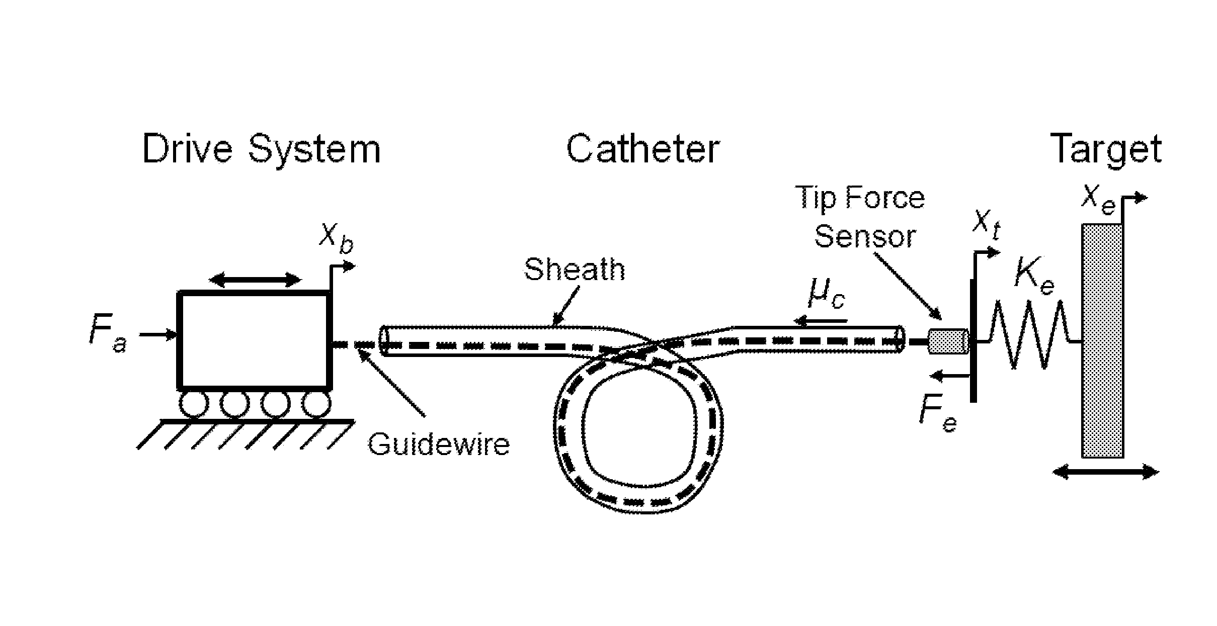
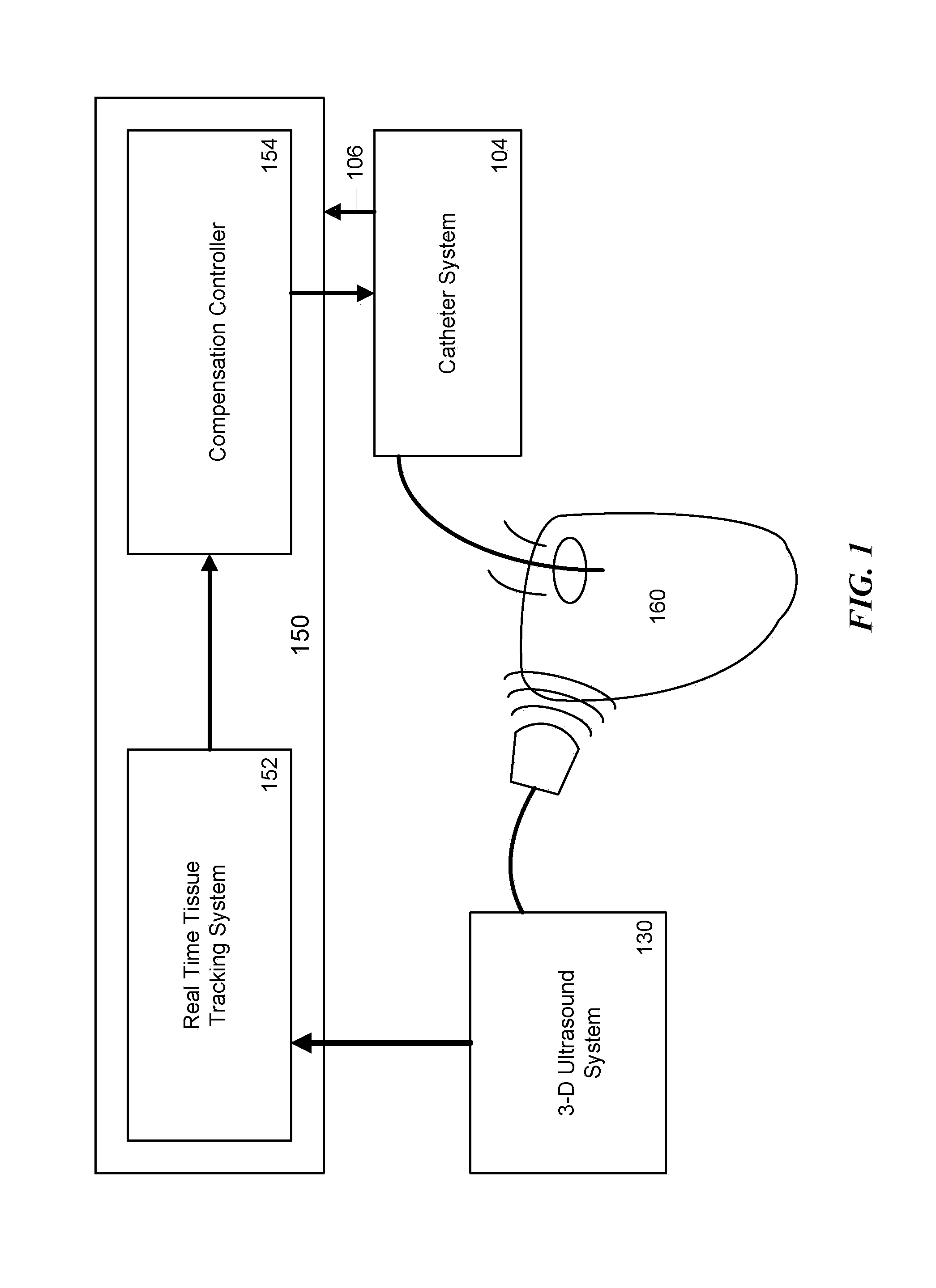
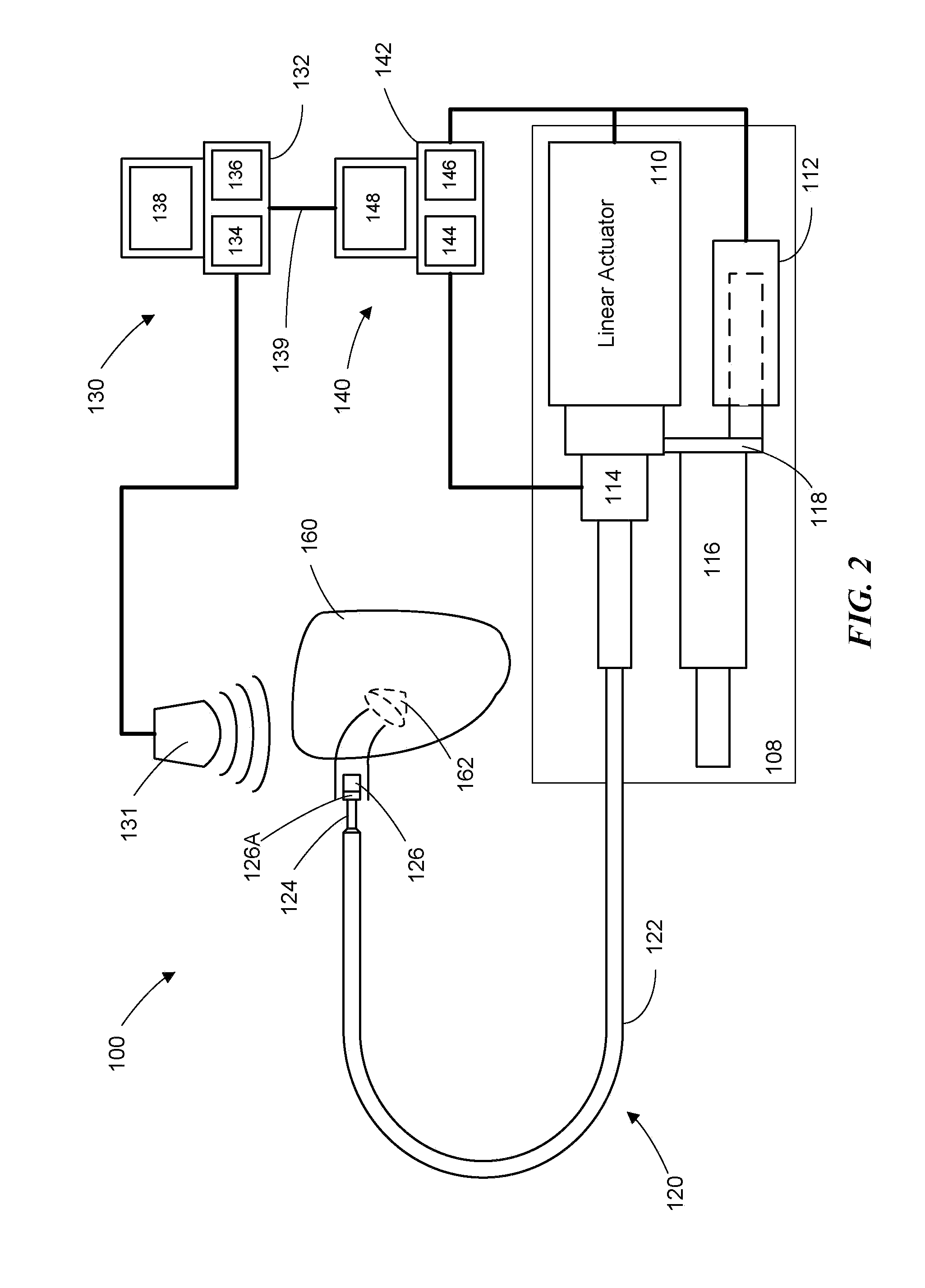
[0044]This present invention is directed to a catheter system that employs motion compensation techniques and optionally, other corrections, in order to minimize invasiveness in surgical procedures involving moving target areas, tissue and organs, such as a beating heart. In accordance with one embodiment of the invention, the system includes an actuator at the base of the catheter system that can drive a catheter guide-wire inside the flexible catheter sheath. For example, the sheath can be manually or automatically manually advanced through the vasculature into the heart. A standard 3-D ultrasound (3DUS) probe can be used to produce images of the catheter tip and the tissue target, and real-time image processing algorithms can be used to track the catheter-tissue relationship and control the motion of the catheter guide-wire tip. The guide-wire tip can be translated in and out of the sheath in correspondence with the cardiac motion to perform repairs. A control system can be used ...


PUM

PropertyMeasurementUnit
accelerationaaaaaaaaaa
speedsaaaaaaaaaa
widthaaaaaaaaaa

Abstract

A catheter system allows for percutaneous intervention on the fast-moving structures inside the heart. The device consists of a steerable catheter sheath, an actuated, multi-degree of freedom moving catheter, and a catheter end effector, such as a fixation device. An actuator controls the motion of the catheter guide-wire in the catheter sheath to follow the motion of the target tissue. A control system controls the actuator and compensates for mechanical characteristics of the system including friction and backlash. A 3-D imaging system can be used to view the motion of the target tissue and the catheter end effector and produce 3-D imaging data. The 3-D imaging data can be used by the control system to track the target tissue and accurately position the end effector with respect to the moving target tissue allowing a clinician to repair the target tissue while it is moving. The system can be used to perform mitral valve annuloplasty wherein the actuated catheter compensates for the heart valve motion and an end effector fixation device is used to place fixation items, like anchors or staples, into the heart valve tissue to fix the annulus.

Description

CROSS-REFERENCE TO RELATED APPLICATIONS[0001]This application claims any and all benefits as provided by law of U.S. Provisional Application Nos. 61 / 329,803 filed 30 Apr. 2010 and 61 / 388,813 filed 1 Oct. 2010, which are hereby incorporated by reference in their entirety.STATEMENT REGARDING FEDERALLY SPONSORED RESEARCH[0002]This invention was made with government support under HL073647 awarded by the National Institutes of Health. The government has certain rights in this invention.REFERENCE TO MICROFICHE APPENDIX[0003]Not ApplicableBACKGROUND[0004]1. Technical Field of the Invention[0005]The present invention is directed to a catheter device for use in percutaneous surgery. Specifically, the invention is direct to a motion compensated catheter device for use in surgery on fast moving structures of the body, such as a beating heart.[0006]2. Description of the Prior Art[0007]Catheter technology has greatly expanded the range of surgical procedures that can be performed with minimal in...

Claims


Application Information

Patent Timeline
Patent Type & Authority Applications(United States)
IPC IPC(8): A61M25/01
CPCA61B8/0841A61B8/483A61B8/565A61B19/5244A61M25/0045A61M25/0105A61M25/0116A61M25/0133A61M25/0147A61M2025/0046A61M2025/0166A61M2025/0681A61M25/0113A61B34/20
Inventor KESNER, SAMUELHOWE, ROBERTYUEN, SHELTONDEL NIDO, PEDROPERRIN, DOUGLASVASILYEV, NIKOLAY
Owner PRESIDENT & FELLOWS OF HARVARD COLLEGE
Learn More