
System and Method of Extending the Communication Range in a Visible Light Communication System

a communication system and visible light technology, applied in the field of visible light communication system, can solve the problems of increasing the cost of the lighting control system, and being subject to being lost, so as to minimize the probability of such devices responding, and limit the communication rang

Active Publication Date: 2013-07-18
LUTRON TECH CO LLC
View PDF18 Cites 110 Cited by
  • Summary
  • Abstract
  • Description
  • Claims
  • Application Information

AI Technical Summary

Benefits of technology

This patent describes a remote control device that uses a camera to detect light emitted from controlled devices. By using an image sensor, instead of a discrete LED or photodiode, the device can identify the location of many light sources and track changes in brightness and color over time. This allows the device to receive data or messages from multiple devices simultaneously. Additionally, the patent discusses a technique called CRC checksum, which ensures error protection and allows a device manufacturer to communicate with only their own devices. This is done by programming a unique ID into each controlled device and using it as a seed for the CRC checksum.

Problems solved by technology

Universal remote controllers have had some success combining functions in one handheld device; however, they are expensive, cumbersome, and subject to being lost.
However, these remote controllers typically use infrared physical layers, which require the light fixtures to have infrared transceivers.
This inevitably increases the cost of the lighting control system.
A limitation of the visible light communication protocol, and specifically, a protocol that transmits optical data using visible light traveling through free space, is that it is typically limited in communication range and generally restricted to line of sight.
In other words, optical data transmitted through free space typically cannot be communicated around corners or through walls between various rooms in a building, or between light fixtures and other devices that are too far away and outside of the optical communication range of the remote control device.

Method used


Image

  • System and Method of Extending the Communication Range in a Visible Light Communication System
  • System and Method of Extending the Communication Range in a Visible Light Communication System
  • System and Method of Extending the Communication Range in a Visible Light Communication System

Examples


Embodiment Construction

[0068]Smart phones with touch screen displays and cameras with LED flash are becoming commonplace, and typically include radio frequency (RF) transceivers for communicating bi-directionally, using the RF spectrum, according to cellular phone protocols for long-range communication and Bluetooth protocols for short-range communication. Smart phones are not used to control lighting fixtures in conventional infrared-based lighting control systems, because they do not contain the infrared transceivers necessary for interfacing with these systems.

[0069]Recently, smart phones have been used to in lighting control systems to communicate with lighting fixtures, or with specialized appliances attached to the fixtures, using radio frequency signals transmitted, e.g., from a Bluetooth radio. However, these lighting control systems require the controlled devices (i.e., the lighting fixtures or the specialized appliances) to also include relatively expensive and limited-range Bluetooth radios. A ...


PUM


Abstract

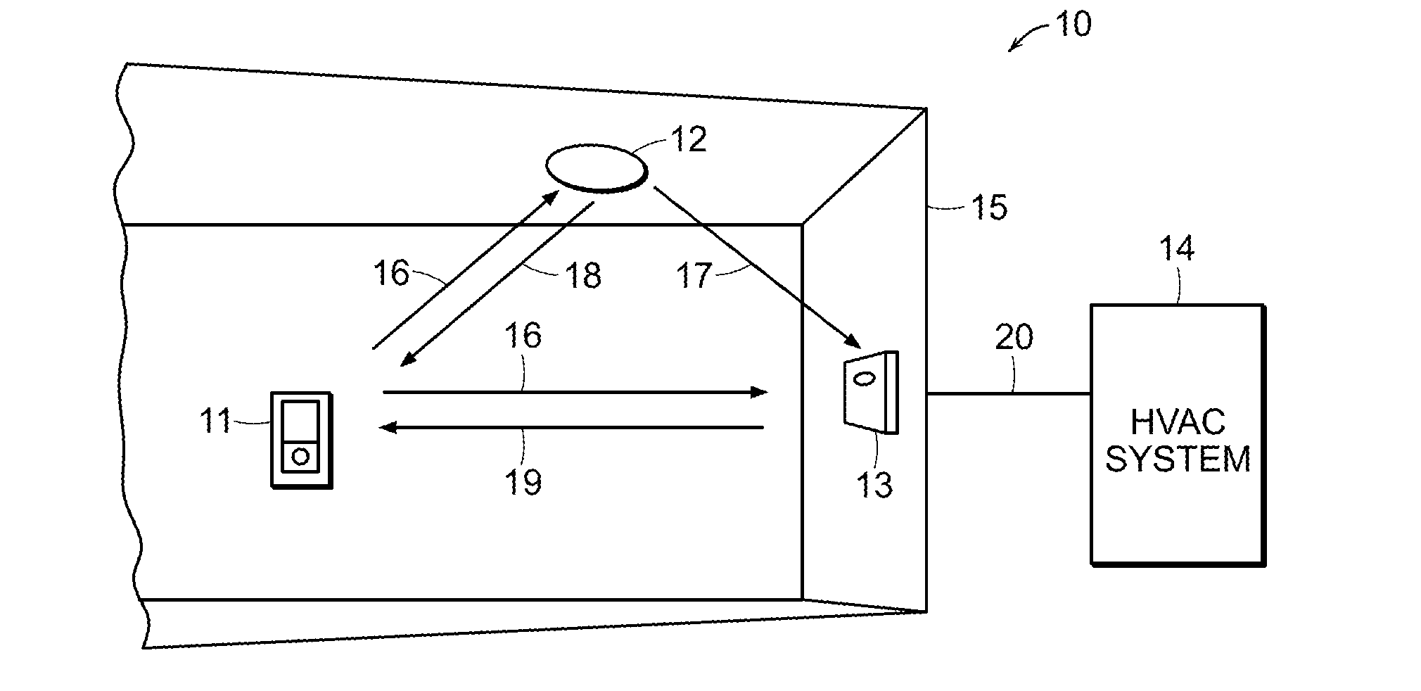
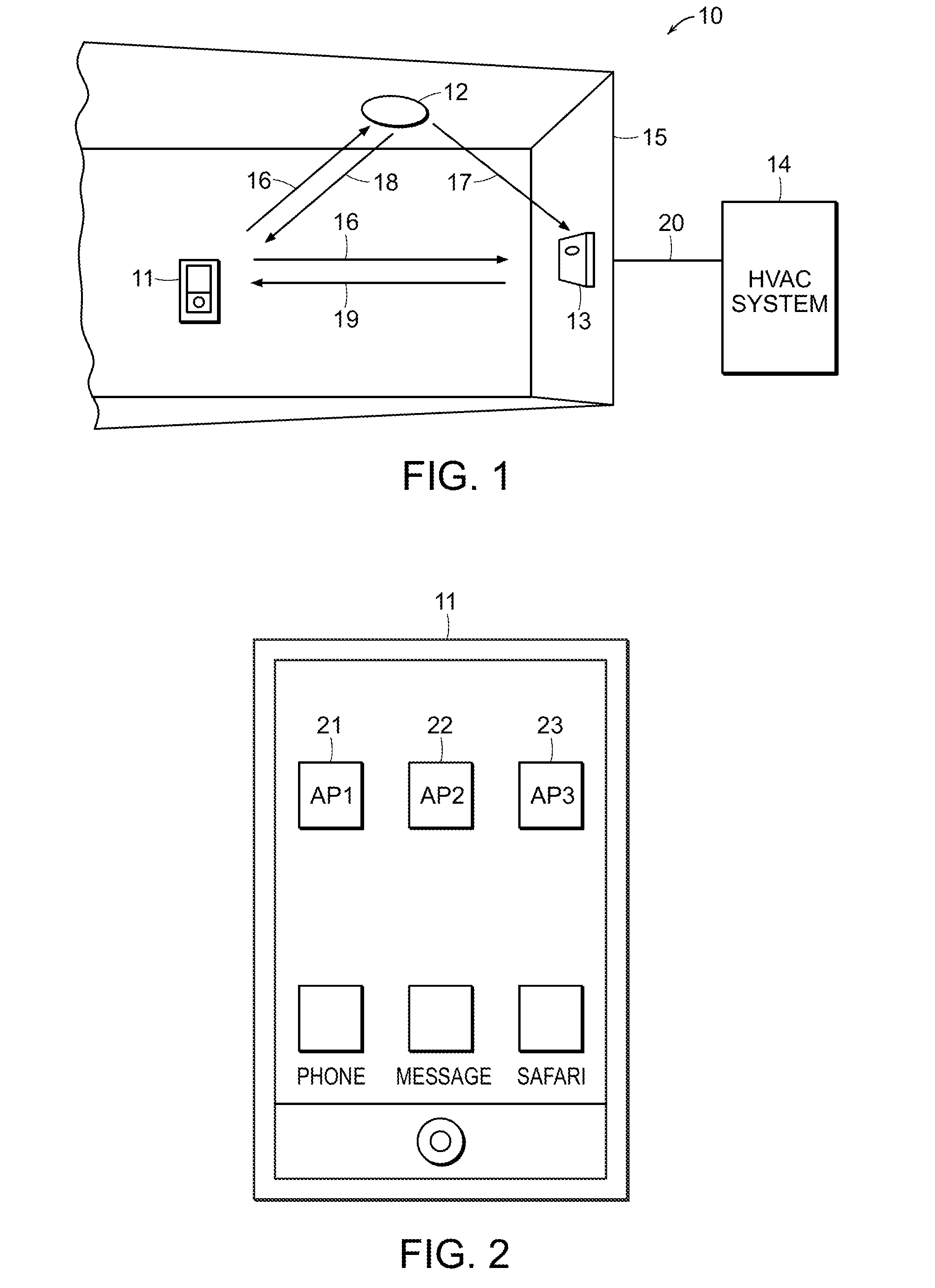
A system, remote control device and method are provided herein for communicating with and controlling various devices using visible light communication (VLC). According to one embodiment, a method is provided for extending a communication range of a visible light communication system comprising a remote control device and a plurality of controlled devices. Such a method may include, for example, transmitting a communication message from a remote control device to a first controlled device located within range of the remote control device, wherein the communication message is transmitted through free space using visible light, and extending the communication range of the visible light communication system to a second controlled device, which is located outside of the range of the remote control device, by using the first controlled device to retransmit the communication message through free space using visible light to the second controlled device.

Description

PRIORITY CLAIM[0001]The present application claims priority to U.S. Provisional Application No. 61 / 601,153 filed Feb. 21, 2013. The present application is further a continuation-in-part of U.S. patent application Ser. No. 13 / 231,077 filed Sep. 13, 2011.BACKGROUND OF THE INVENTION[0002]1. Field of the Invention[0003]This invention relates to visible light communication system and, more particularly, to using remote control devices with cameras to communicate with controlled devices using visible light.[0004]2. Description of Related Art[0005]Remote controllers have become ubiquitous for controlling all sorts of electronic components including TVs, sound systems, ceiling fans, projectors, computers, thermostats, lighting systems, etc. However, each remote controller is typically unique for the particular associated electronic device. Universal remote controllers have had some success combining functions in one handheld device; however, they are expensive, cumbersome, and subject to be...

Claims


Application Information

Patent Timeline
Patent Type & Authority Applications(United States)
IPC IPC(8): G08C23/04
CPCG08C23/04H04B10/116H04L12/282H04L12/6418G08C2201/93H04L2012/285H04L12/2838H04L2012/2841H05B37/0245H05B47/195H05B47/1965
Inventor KNAPP, DAVID J.HO, HORACE C.
Owner LUTRON TECH CO LLC
Learn More