
Electronic apparatus for measuring the patellar reflex and other reflexes

a patellar reflex and electronic equipment technology, applied in the field of electronic instruments, can solve problems such as affecting the measurement accuracy, complex construction, and affecting the mobility of patients

Inactive Publication Date: 2013-07-04
RIVAS PERLWITZ GERARDO ANDRES +1
View PDF7 Cites 2 Cited by
  • Summary
  • Abstract
  • Description
  • Claims
  • Application Information

AI Technical Summary

Benefits of technology

The invention allows for a completely definitive measurement of reflex responses without causing any pain or discomfort to the patient. It is also able to produce results quickly and automatically calculate relevant parameters.

Problems solved by technology

In its modern-day versions, these devices incorporate electronics and computers, but are still complex to build and their size prevents them from being portable.
There are instruments in the current state of the art specifically intended for measuring reflexes, but their size makes them invasive, hampering the patient's mobility.
The size of the device is such that the resulting system affects the mobility of a leg, thereby altering the measurements.
There are also earlier academic papers that report the use of MEMS accelerometers to measure the dynamic variables of reflex movements, but these papers have not materialised into commercial devices.
None of these developments, patents or lines of research have given rise to portable devices capable of measuring and processing the signals in real time, due to which doctors do not have devices that are easy to use and can be objectively interpreted to measure the patellar reflex.

Method used


Image

  • Electronic apparatus for measuring the patellar reflex and other reflexes
  • Electronic apparatus for measuring the patellar reflex and other reflexes

Examples


Embodiment Construction

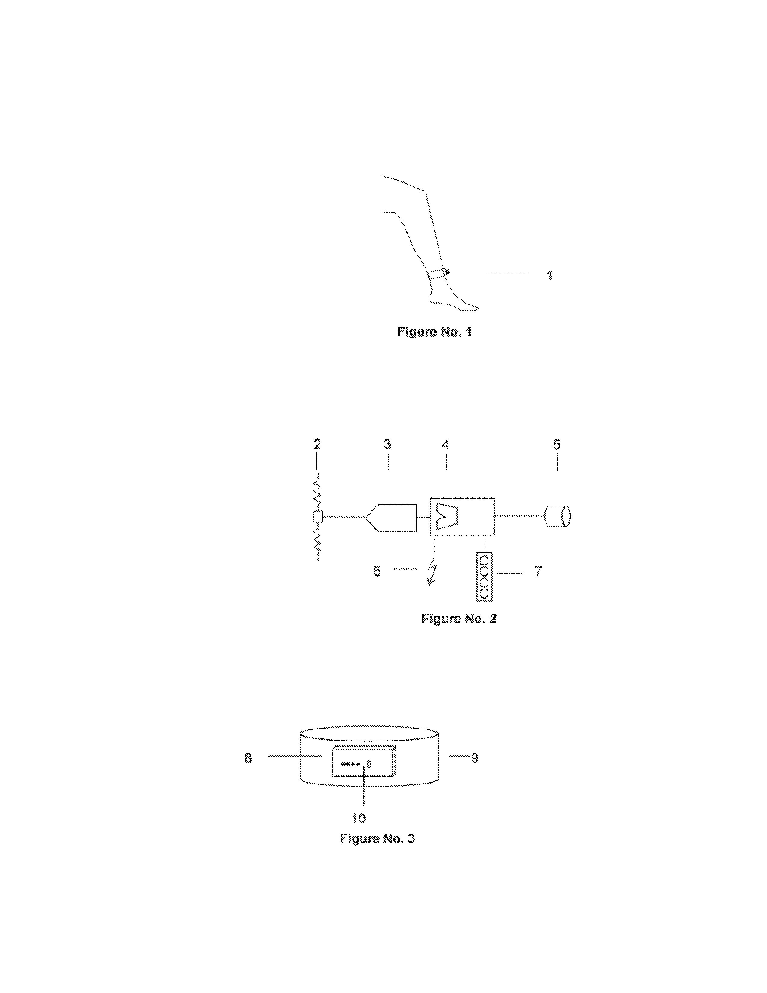
[0021]In all the embodiments of the invention, a device containing at least one sensor is fixed to the patient's ankle or leg to measure limb movement variables. In this description, the sensor used is an integrated MEMS accelerometer.

[0022]When the leg moves, the accelerometer records the acceleration. Given that the movement is pendular, i.e. the knee remains fixed in its position while the leg moves, this angular acceleration translates into a linear tangential acceleration equal to ωR and a radial acceleration equal to ω2R, where ω is the instant rotation speed and R is the distance between the knee and the place where the sensor is fixed. The sensor records the linear and radial accelerations, together with the gravitational acceleration which, for this embodiment, is an alteration that must be considered during mathematical processing.

[0023]In one embodiment of the invention, a numerical analogue converter is used to sample the accelerometer's output signal at a sampling frequ...


PUM


Abstract

The invention belongs to the field of electronic instruments for measuring physiological parameters and medical diagnosis.The patellar reflex is a fundamental part of neurological examination when analysing damage to peripheral neurological structures with central medullary integration.At present, this reflex is visually assessed by the practitioner. In addition, it would be of interest to the practitioner to obtain information relating to latency and whether the reflex is polykinetic, parameters which are difficult to assess visually. The instruments of the current state of the art are disruptive to the patient, are complicated to position and / or they provide unprocessed information.The invention enables the reflex to be objectively measured, is minimally disruptive to the patient and calculates the relevant parameters immediately and automatically. It incorporates sensors, electronics, numerical signal processing for the extraction of parameters and elements for delivering the information. The invention is supplemented with the transmission of data to the neurologist via the Internet.

Description

TECHNICAL FIELD[0001]The present invention relates to the field of electronic instruments applied to the measurement of human physiological parameters and medical diagnosis.PRIOR ART[0002]The patellar reflex is a fundamental part of neurological examination when analysing possible damage to peripheral neurological structures (afferent sensory neuron and efferent motor neuron) with central medullary integration.[0003]The reflex travels through afferent sensory fibres, it is integrated at medullar level and sends its efferent motor response via motor fibres which in this case innervate the quadriceps muscle, which contracts suddenly, completing the reflex arc.[0004]The method currently used to assess the patellar reflex is the following. The patient is sitting or lying down with the knee flexed and relaxed. The medical practitioner taps the tendon of the femoral quadriceps immediately below the knee cap with a hammer. This percussion causes the muscle tendon to stretch, responding wit...

Claims


Application Information

Patent Timeline
Patent Type & Authority Applications(United States)
IPC IPC(8): A61B5/11
CPCA61B5/1107A61B9/005A61B5/6829A61B5/4585A61B5/1118
Inventor RIVAS PERLWITZ, GERARDO ANDRESAGUILERA ARRIAGADA, CARLOS HUMBERTO
Owner RIVAS PERLWITZ GERARDO ANDRES
Learn More