
Illuminated Dental Prop

a dental prop and light source technology, applied in the field of illumination dental props, can solve the problem that the light source is not readily removable from the bite block, and achieve the effect of improving the patient's comfort and comfor

Active Publication Date: 2013-06-27
KHOURI LOUIE
View PDF1 Cites 4 Cited by
  • Summary
  • Abstract
  • Description
  • Claims
  • Application Information

AI Technical Summary

Benefits of technology

The present invention is an illuminated dental prop that can hold a dental patient's mouth open during dental procedures. It incorporates a removable light source that can be easily sterilized and discarded. The dental prop is designed to be fully contained within the patient's mouth, without any wires extending out, to ensure that the practitioner can access the target area with the necessary dental instruments. The technical effect of this invention is the provision of a convenient and effective tool for dental procedures that allows for better visibility and access without compromising the patient's comfort.

Problems solved by technology

A perceived problem with each of the above-referenced teachings is that the light source is not readily removable from the bite block such that the bite block portion can be sterilized or discarded after a single use.
Further, the light assembly is either integral with the bite block portion or requires extreme work to detach the same from the bite block.

Method used


Image

  • Illuminated Dental Prop
  • Illuminated Dental Prop
  • Illuminated Dental Prop

Examples


first embodiment

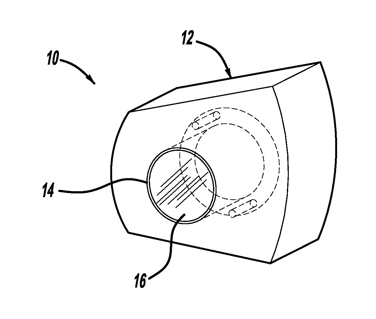
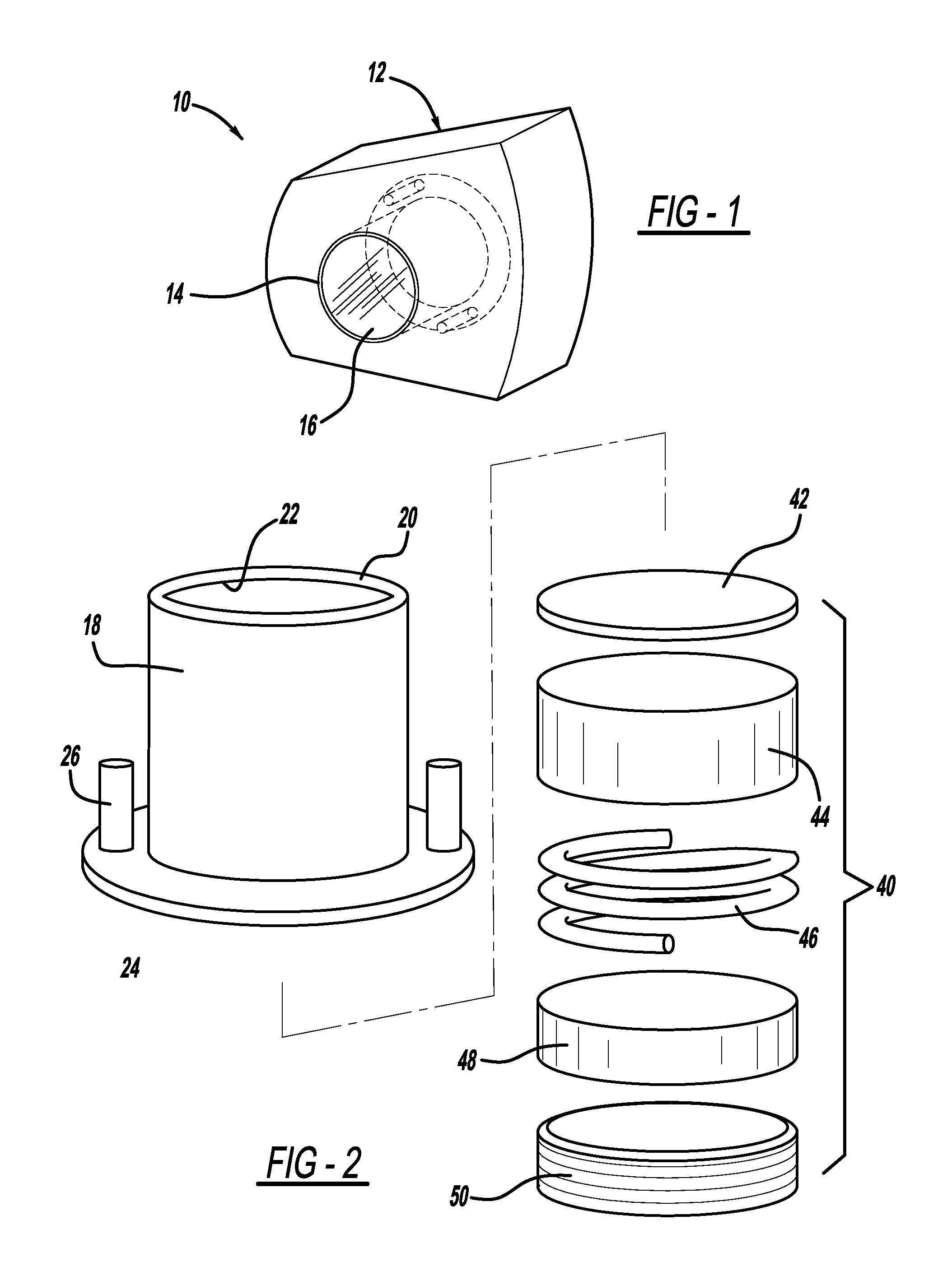
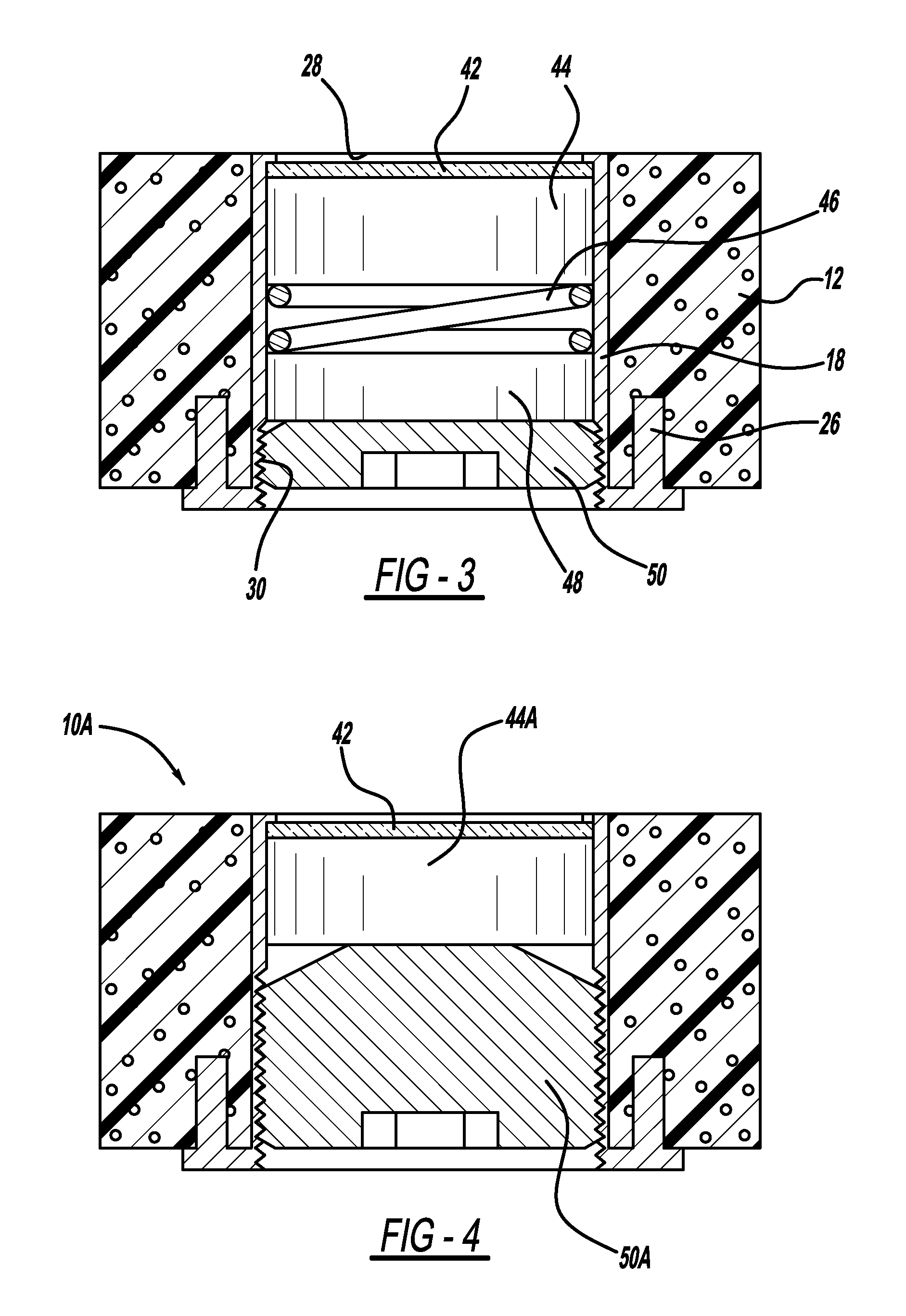
[0025]The first illuminated dental prop in accordance with the teachings of the present invention is shown with reference to FIGS. 1-3. Initially, referring to FIG. 1, there is shown the illuminated dental prop 10 which includes a body 12 which forms the bite block portion of the assembly and a light assembly 16 which is mounted through an aperture 14 of the body 12. The body 12 can be in many shapes or configurations and is shown as a wedge-shaped bite block having upper and lower teeth engaging surfaces. The light assembly 16 which is selectively detachable from the body of the bite block generally includes a housing 18 and a light source 40. The housing 18 includes a sleeve 20 including a longitudinally central bore 22 for hosting the light source 40. The sleeve 20 includes in inwardly extending lip 28 at one end and a threaded interior lead-in portion 30 along the opposite end of lip 28. The housing 18 also includes an integral outwardly extending flange disposed along the end ...

embodiment 100

[0038]Referring to FIGS. 10-12, there is shown an alternative illuminated dental prop embodiment 100 including two major components, a bite prop 112 and a light assembly 114. The light assembly, as with other embodiments shown herein, includes as its main components a housing 138 and a lighting source 140. The housing can be formed from a variety of materials sufficient to protect the lighting package secured within, such as lightweight thermoplastics, thermosets or silicone, by way of non-limiting example. The light source is preferably a LED light.

[0039]As shown, the lighting assembly housing 138 has an exterior wall 144 defined by a front wall 146, rear wall 148 and opposing top and bottom walls 150, 150A, respectively. The top and bottom walls in the embodiment shown are mirror images, both including a recess 152 which receives the tabs 126 projecting from the interior wall of the bite prop. The top and bottom walls also include a flange 154 located proximate to the front wall 1...


PUM


Abstract

The present invention relates to an illuminated dental prop for holding a patient's mouth open during dental procedures. The illuminated dental prop is completely disposed within the patient's mouth during use and includes a body portion and a lighting assembly that is selectively detachable from the body to allow for intense sterilization of the components after use. Under certain embodiments of the invention, the body portion and / or the lighting assembly will be disposable after a single use.

Description

BACKGROUND[0001]1. Field of the Invention[0002]The present invention generally relates to illuminated dental props for holding the mouth open during dental procedures. Dental props, per se, are known to come in a variety of shapes and sizes such as wedge-shaped props and C-shaped props by way of non-limiting example. Generally the props are placed between the upper and lower teeth, opposite the side of the mouth which needs to be accessed by a dental practitioner. However, with regard to accessing and viewing the target area by the dental practitioner, currently available dental props do nothing to enhance the visibility within the oral cavity to carryout the necessary procedure.[0003]Further, while various light sources are available to assist in illuminating the oral cavity, such devices are positioned outside of the oral cavity with the light source directed at the target area. However, external light sources tend to be somewhat ineffective. Thus, the present invention relates to...

Claims


Application Information

Patent Timeline
Patent Type & Authority Applications(United States)
IPC IPC(8): A61B1/24A61C5/14A61B1/06
CPCA61B1/24A61C5/14A61B1/0684A61C1/088A61C5/90
Inventor KHOURI, LOUIE
Owner KHOURI LOUIE
Learn More