
Screwdriver hanging assembly

a screwdriver and assembly technology, applied in the field of screwdriver hanging assembly, can solve the problems of increased manufacturing cost and inconvenience, and achieve the effect of saving time for assembling

Inactive Publication Date: 2013-06-20
KAO JUI CHIEN
View PDF0 Cites 19 Cited by
  • Summary
  • Abstract
  • Description
  • Claims
  • Application Information

AI Technical Summary

Benefits of technology

The invention is a screwdriver hanging assembly that saves time and reduces manufacturing costs. It consists of a main frame and two connecting devices that can hold multiple screwdrivers. The main frame has track grooves that the connecting devices fit into, making assembly easy and quick. The technical effects of this invention are improved assembly efficiency and cost-effectiveness.

Problems solved by technology

However, the connecting devices have to be attached to the main frame one by one, so to assemble the multiple connecting devices onto the main frame is time-consuming, increases manufacturing cost and is not convenient.

Method used


Image

  • Screwdriver hanging assembly
  • Screwdriver hanging assembly
  • Screwdriver hanging assembly

Examples


first embodiment

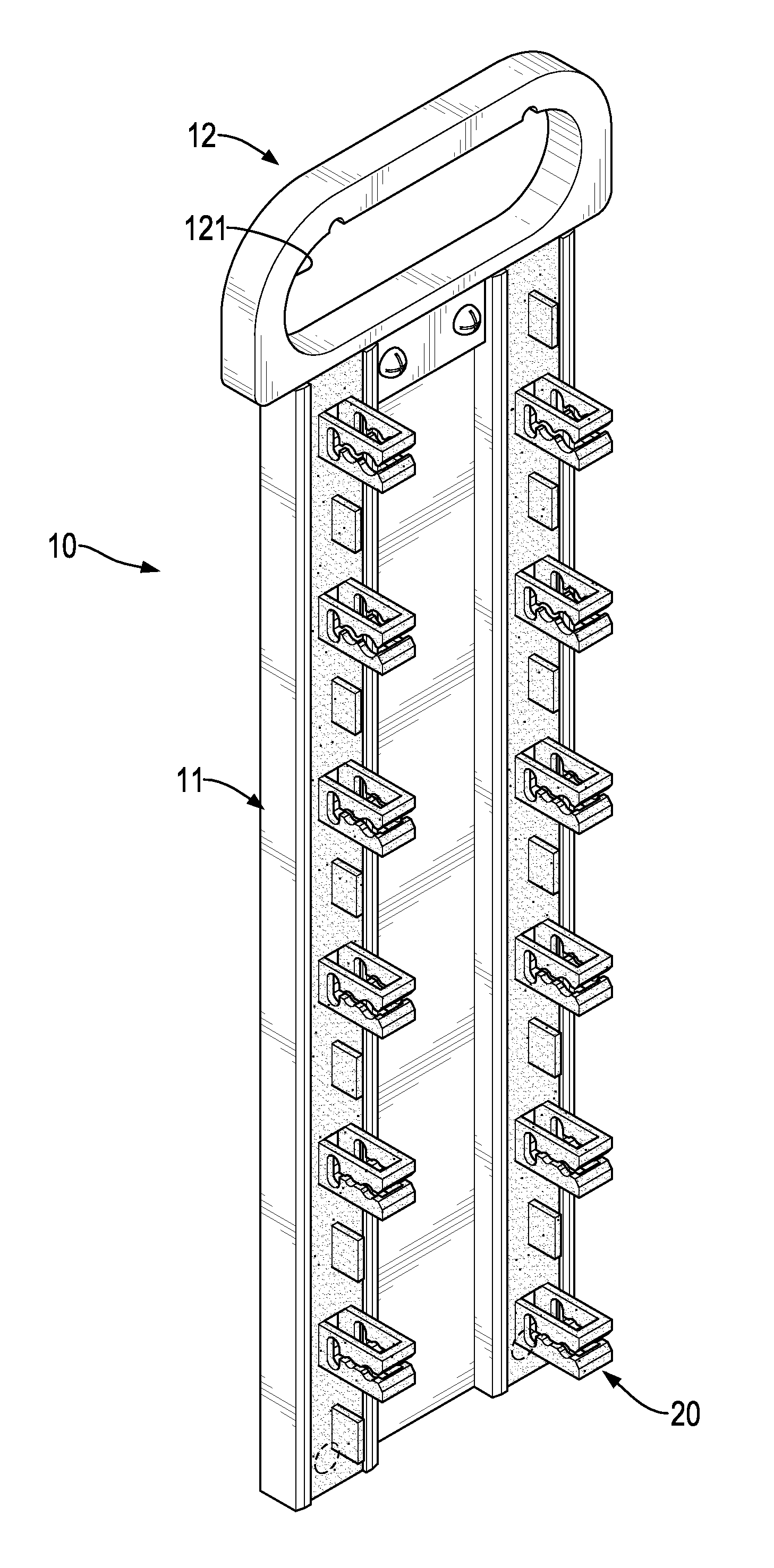
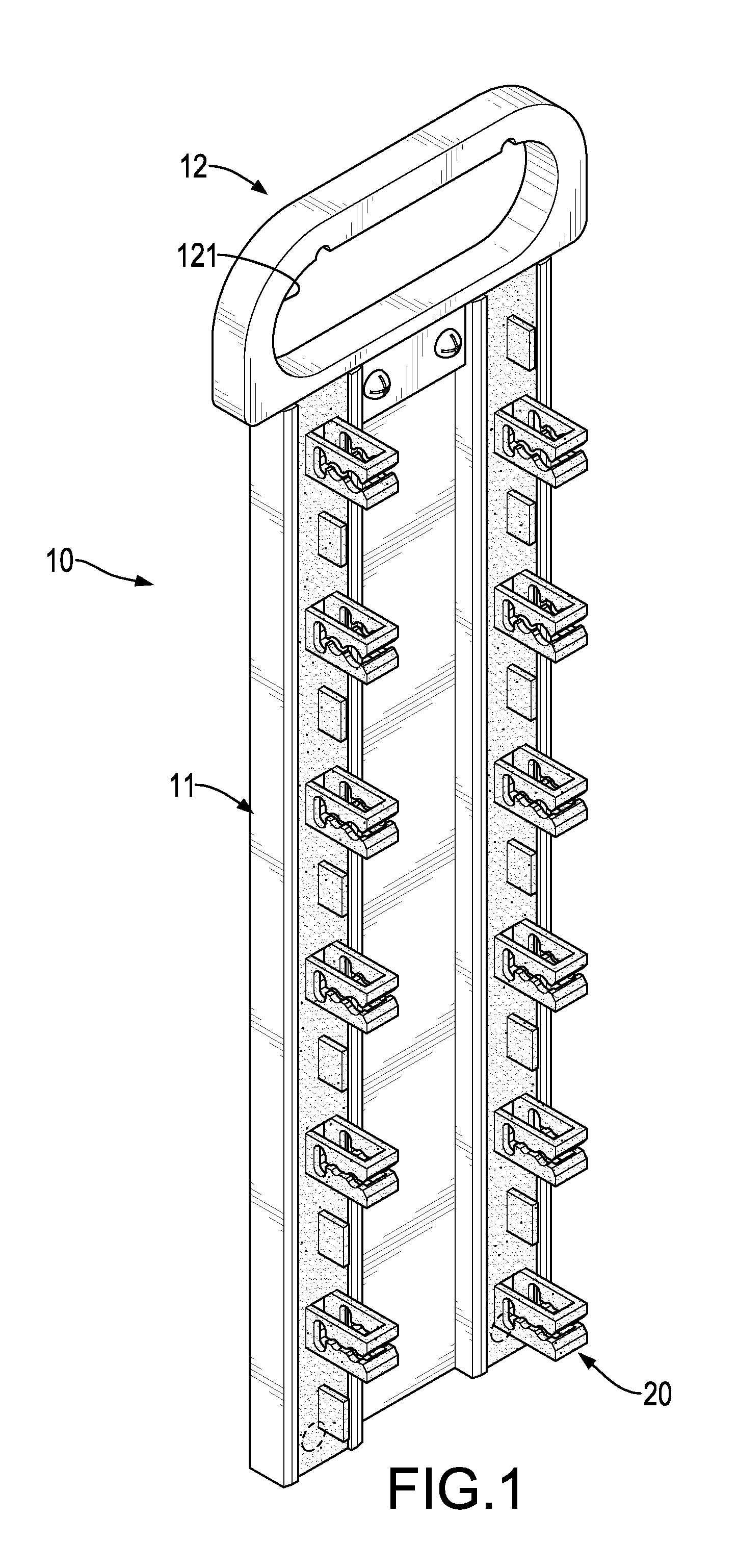
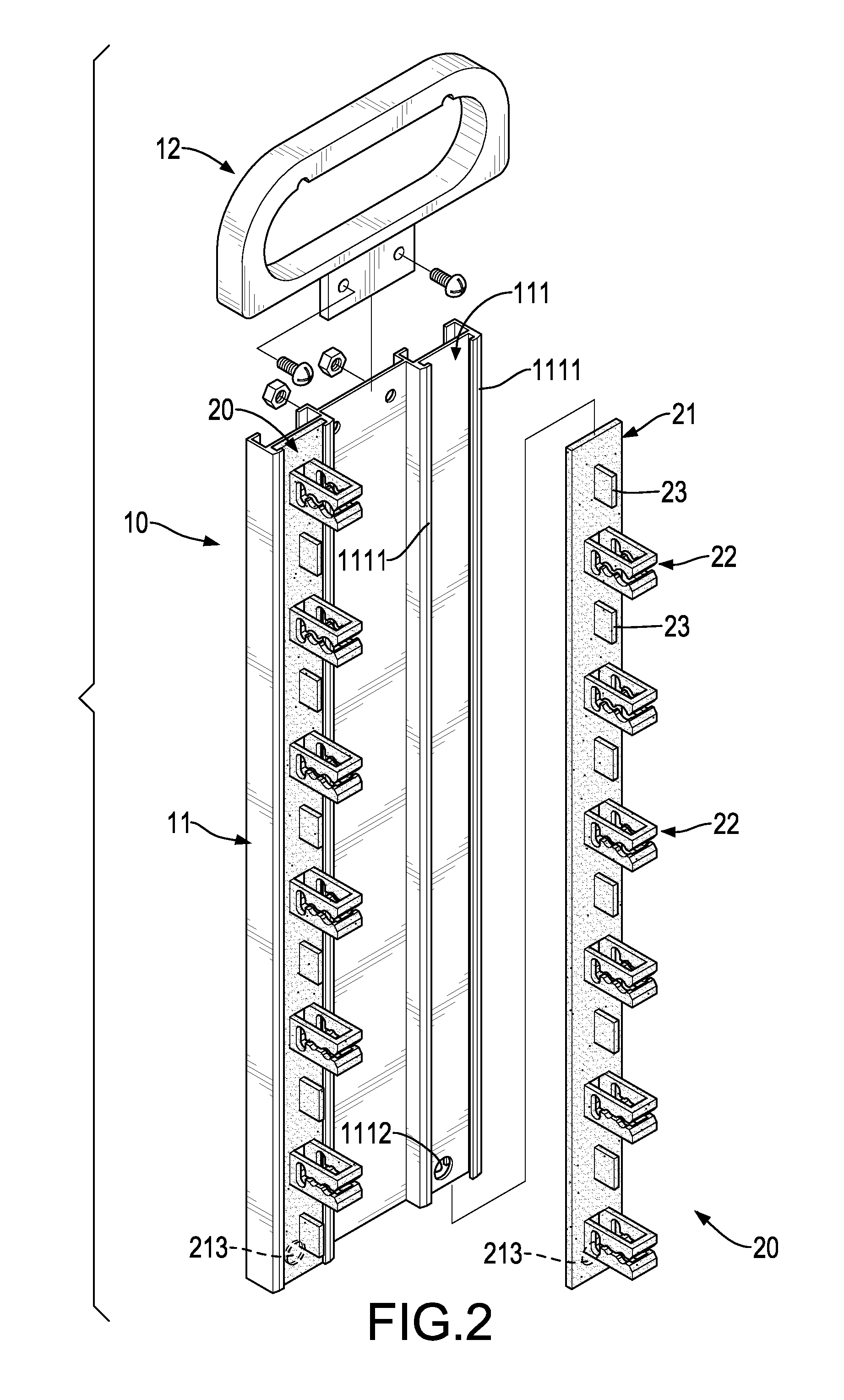
[0028]With reference to FIGS. 1 and 2, a screwdriver hanging assembly in accordance with the present invention comprises a main frame 10 and two connecting devices 20.

[0029]With reference to FIGS. 1, 2 and 5, the main frame 10 has a main plate 11 and a hanging plate 12. The main plate 11 has a rectangular cross section and has two track grooves 111. The track grooves 111 are longitudinally elongated and are parallel to each other. Each track groove 111 has two edges, a bottom, two opposite inner surfaces, two strips 1111 and a positioning hole 1112. The edges of each track groove 111 are longitudinally elongated. A distance between the inner surfaces of each track groove 111 is defined as a first width A.

[0030]The two elongated strips 1111 of each track groove 111 are longitudinally elongated, are parallel to each other and are respectively and integrally connected with the edges of the track groove 111. A distance between the strips 1111 of each track groove 111 is defined as a sec...

second embodiment

[0046]the screwdriver hanging assembly does not have the enlarged holes 221, the first shank holes 222, the second shank holes 223, the bracket openings 224 and the chunks 23. Each bracket 22C has a slot 226C and a through hole 227C. The slot 226C of each bracket 22C is elongated, is formed through the bracket 22C and has a central segment. The through hole 227C of each bracket 22C is formed through the bracket 22C at the central segment of the slot 226C, communicates with the slot 226C and has a round cross section.

[0047]Each connecting device 20C has multiple spaces 24C formed between the brackets 22C of the connecting device 20C at intervals, wherein the spaces 24C of the first connecting device respectively align with the brackets 22C of the second connecting device and the brackets 22C of the first connecting device respectively align with the spaces 24C of the second connecting device.

[0048]With reference to FIGS. 15 to 18, accordingly, a distal tip of a shank S1 of a screwdri...


PUM


Abstract

A screwdriver hanging assembly has a main frame and two connecting devices. The main frame has two track grooves formed in the main frame and parallel to each other. The connecting devices are respectively connected with the track grooves. Each connecting device has multiple brackets for holding multiple screwdrivers. Because combining the connecting devices having the multiple brackets with the main frame is easy, to assemble the connecting devices with the main frame is quick, reduces manufacturing cost and is convenient for holding multiple screwdrivers.

Description

BACKGROUND OF THE INVENTION[0001]1. Field of the Invention[0002]The present invention relates to a screwdriver hanging assembly, and more particularly to a screwdriver hanging assembly to save time for assembling.[0003]2. Description of Related Art[0004]A conventional tool hanger assembly has a main frame and multiple connecting devices. The main frame has two track grooves formed in the main frame and parallel to each other. The connecting devices are slidably mounted on the track grooves. Each connecting device has a bracket protruding from the connecting device and being capable of holding a screwdriver.[0005]However, the connecting devices have to be attached to the main frame one by one, so to assemble the multiple connecting devices onto the main frame is time-consuming, increases manufacturing cost and is not convenient.[0006]To overcome the shortcomings, the present invention tends to provide a screwdriver hanging assembly to mitigate the aforementioned problems.SUMMARY OF T...

Claims


Application Information

Patent Timeline
IPC IPC(8): A47B81/00
CPCB25H3/04
Inventor KAO, JUI-CHIEN
Owner KAO JUI CHIEN
Learn More