Fiber composite component assembly having at least two plate-shaped composite structures and processes for preparing same

a composite component and plate-shaped technology, applied in the field of fiber composite component assemblies, can solve the problems of increasing production expenditure and requiring additional reinforcement of connections, and achieve the effect of high load and damage toleran

Inactive Publication Date: 2013-06-13
AIRBUS OPERATIONS GMBH
View PDF4 Cites 2 Cited by
  • Summary
  • Abstract
  • Description
  • Claims
  • Application Information

AI Technical Summary

Benefits of technology

[0011]An aspect of the invention, provides in a simple manner from the point of view of production technology, to additionally mechanically secure an integral connection, primarily established by bonding, between two plate-shaped composite components to produce a fiber composite component assembly, in order to ensure high tolerance to loads and damage, of the bonded connection area.

Problems solved by technology

In the use of fiber composite components whose fibers comprise carbon, riveting for additional reinforcement of the connection is problematic because CFP is not an isotropic material, and thus a quasi-isotropic layer structure is needed to achieve adequate strength of the hole walls for riveting.
Furthermore, because of the drilling dust arising during riveting, all riveting work needs to be completed prior to commencement of system installation, which increases production expenditure.
On the other hand, other generally-known alternative mechanical reinforcement means, for example pin connections, sewn connections and the like, cannot be placed in already-cured fiber composite components, and therefore they have so far been limited to use in individual components or large-format integral structures.
However, since this technical solution is primarily based on an increase in the shearing strength, its use is limited to special applications that require such increased shearing strength of an adhesive connection between two plate-shaped fiber composite components.

Method used


Image

  • Fiber composite component assembly having at least two plate-shaped composite structures and processes for preparing same
  • Fiber composite component assembly having at least two plate-shaped composite structures and processes for preparing same

Examples


Embodiment Construction

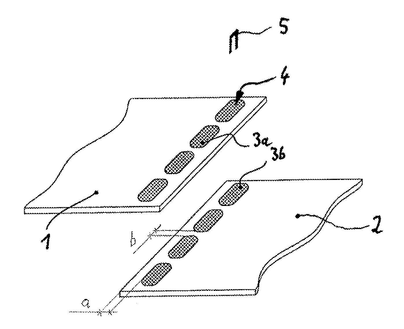
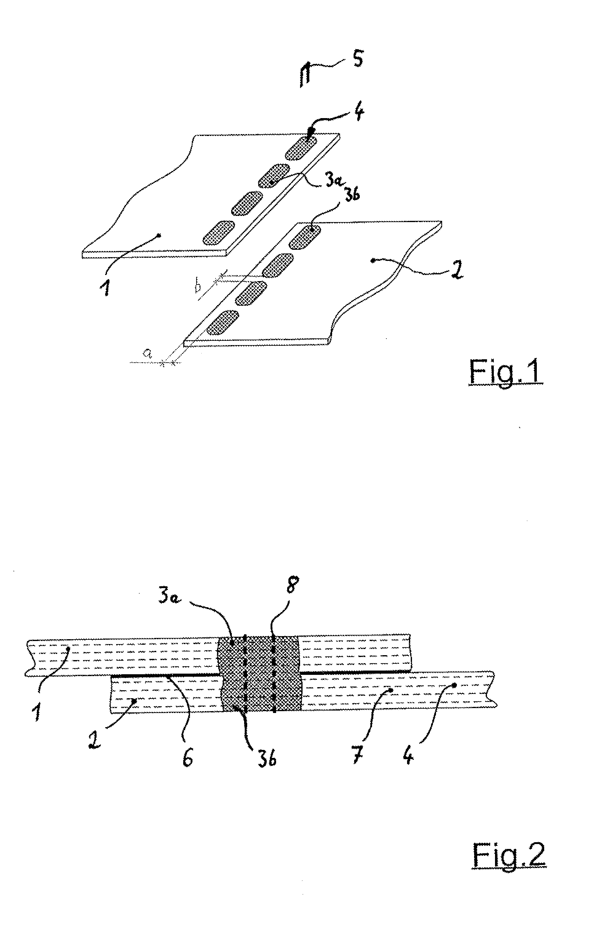
[0024]According to FIG. 1 two plate-shaped composite components 1 and 2 of an aircraft structure (not shown in detail) in the edge region comprise several partial regions 3a or 3b which can be brought to flush conformity with each other and which are arranged so as to be spaced apart from each other. While the fiber composite components 1 and 2 outside these partial regions 3a and 3b are cured, only fibers 4 without a plastic matrix extend through the partial regions 3a and 3b.

[0025]This forms a prerequisite for the two plate-shaped fiber composite components 1 and 2 to be interconnected during installation, by way of additional mechanical reinforcement means in the form of pins 5, in addition to bonding. In this embodiment each partial region 3a, 3b that does not contain synthetic resin is completely enclosed by a cured region of the fiber composite component 1 or 2, thus in each case forming an essentially rectangular region. The partial regions 3a and 3b that do not contain synt...


PUM

PropertyMeasurementUnit
mechanicalaaaaaaaaaa
shapeaaaaaaaaaa
mechanical reinforcementaaaaaaaaaa

Abstract

A fiber composite component assembly includes at least two plate-shaped composite structures which in each case are made from synthetic-resin embedded fibers and are integrally interconnected by way of an adhesive layer arranged in between, and additional mechanical reinforcement means, wherein the fiber composite components include several partial regions that do not contain synthetic resin, which partial regions can be brought to flush conformity with each other and which are arranged so as to be spaced apart from each other, through which partial regions the mechanical reinforcement means that can subsequently be bonded-in with synthetic resin have been passed.

Description

CROSS-REFERENCE TO RELATED APPLICATIONS[0001]This application claims the benefit of the filing date of U.S. Provisional Patent Application No. 61 / 568,689 filed Dec. 9, 2011, the disclosure of which is hereby incorporated herein by reference.TECHNICAL FIELD[0002]The invention relates to a fiber composite component assembly having at least two plate-shaped composite structures which in each case are made from synthetic-resin-embedded fibers and are integrally interconnected by way of an adhesive layer, arranged in-between, and additional mechanical reinforcement means. Furthermore, the invention also relates to a method for producing such a fiber composite component assembly.[0003]The field of application of the invention relates predominantly to aircraft construction. In particular in the production of structural components for aircraft fuselages and the like, plate-shaped fiber composite components can be used. Specifically, in this field carbon-fiber reinforced plastics (CFPs) are ...

Claims


Application Information

Patent Timeline
Patent Type & Authority Applications(United States)
IPC IPC(8): B32B37/02B32B7/08B32B7/12B32B3/06
CPCB32B37/02Y10T428/24033B32B7/08B32B7/12B29C66/21B29C66/3452B29C66/71B29C66/7212B29C66/73752B29C66/73941B29C66/73756B32B3/06Y10T428/197B29C66/721B29C66/43B29C65/48B29C70/845B29C65/564B29C65/62B29C65/72B29C66/1122B29K2307/04B29K2063/00B32B5/06B32B5/26B32B3/02B32B2260/021B32B2260/023B32B2260/046B32B2262/106B32B2605/18Y10T428/249923
Inventor KRUSE, THOMASFIDEAU, PAULIN
Owner AIRBUS OPERATIONS GMBH
Why Eureka
Try Eureka