
Position feedback control for a vitrectomy probe

a technology of feedback control and vitrectomy, which is applied in the field of vitrectomy probe systems, can solve the problems of inconvenient operation, difficult cutting and removal of membranes, and difficult mobile tissue management, and achieve the effects of avoiding inconvenient operation

Inactive Publication Date: 2013-06-06
ALCON RES LTD
View PDF4 Cites 52 Cited by
  • Summary
  • Abstract
  • Description
  • Claims
  • Application Information

AI Technical Summary

Benefits of technology

The present disclosure is about a surgical system that uses position feedback control to cut tissue. The system includes a probe driver and a vitrectomy probe with a cutting mechanism. The cutting mechanism has an inner cutting tube and an outer cutting tube, with the outer cutting tube having a tissue-receiving port. A sensor detects the displacement of the inner cutting tube and sends signals to a controller. The controller analyzes the signals and adjusts the timing of the probe driver accordingly. This ensures precise cutting of tissue. The method also includes setting up the system to detect a target stroke length, receiving an input from a healthcare provider, sensing the actual stroke length, and adjusting the system to match the target stroke length. Overall, the technology enhances the accuracy and efficiency of cutting in surgery.

Problems solved by technology

In particular, delicate operations such as mobile tissue management (e.g. cutting and removal of vitreous near a detached portion of the retina or a retinal tear), vitreous base dissection, and cutting and removal of membranes are particularly difficult.
Variations in characteristics of cutter components, including those from initial critical component tolerances, can introduce inconsistencies in operation and can restrict maximum cut rate potential across vitrectomy probes.
However, as cut rates increase, specifying the appropriate valve timing sequence becomes more challenging because the periods of cycle become smaller with higher cut rates.
Any added margin to the design to ensure the probe closes and opens now begins to restrict the ability to maximize cut rate.

Method used


Image

  • Position feedback control for a vitrectomy probe
  • Position feedback control for a vitrectomy probe
  • Position feedback control for a vitrectomy probe

Examples


Embodiment Construction

[0021]Reference is now made in detail to exemplary embodiments of the invention, examples of which are illustrated in the accompanying drawings. Wherever possible, the same reference numbers are used throughout the drawings to refer to the same or like parts.

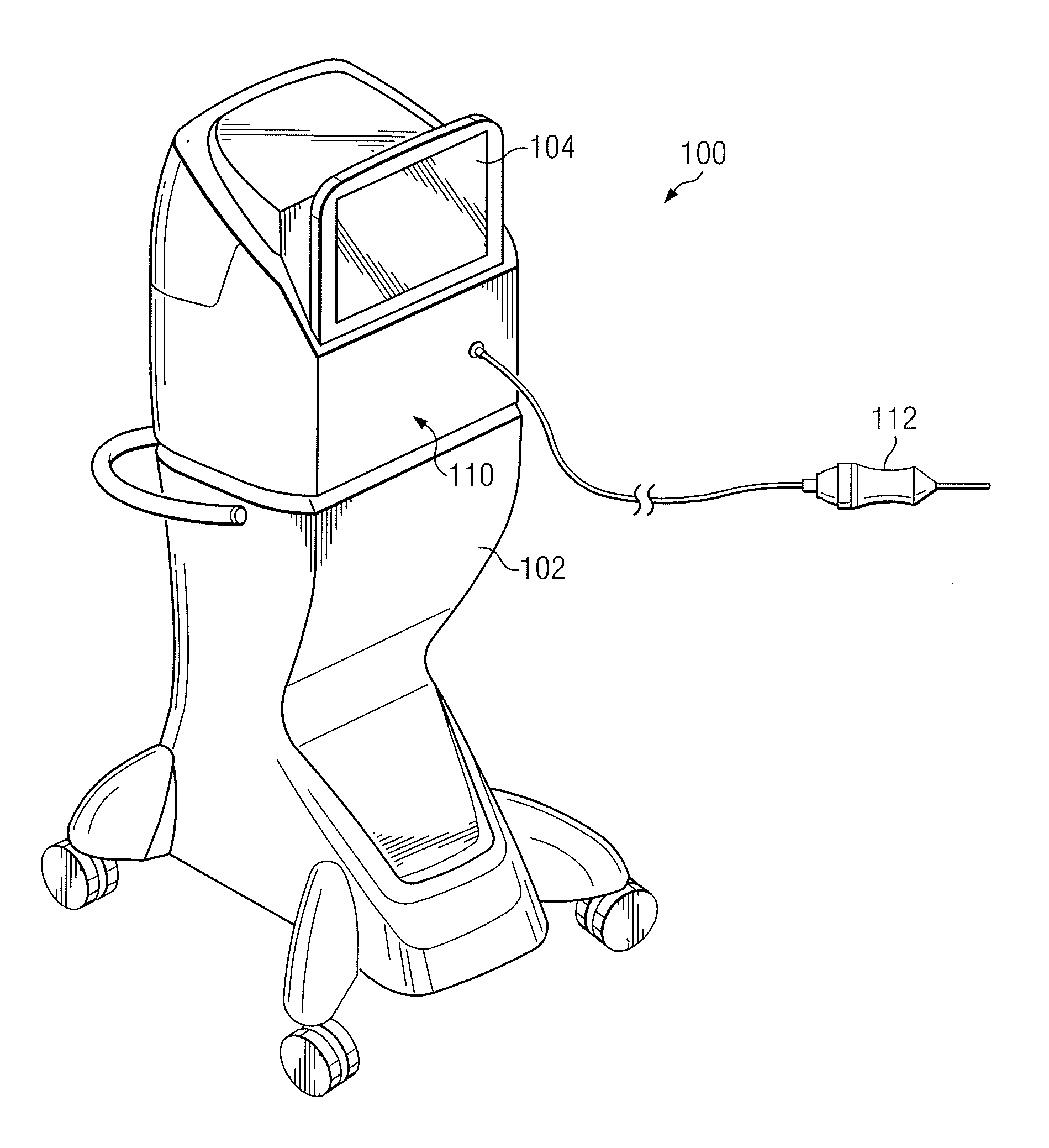
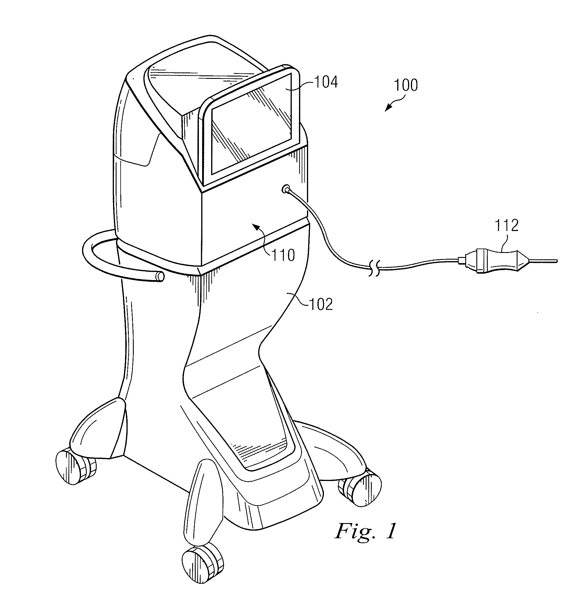
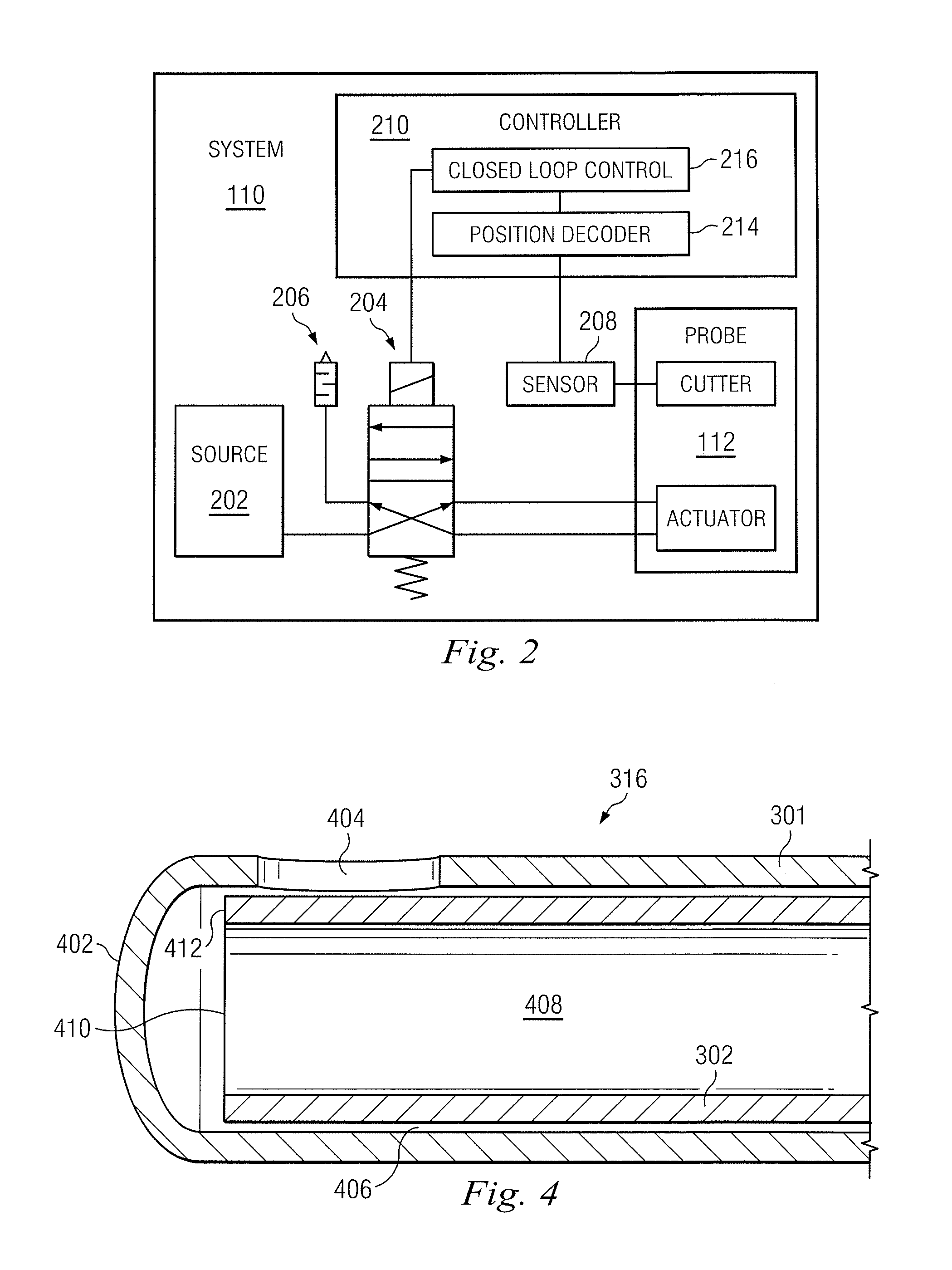
[0022]The present disclosure is directed to a surgical system including a vitrectomy probe for performing ophthalmic surgeries. The surgical system is arranged and configured to use position feedback control to track the probe's cutter movement and to optimize control of the vitrectomy probe. A sensor detects the position of the vitrectomy probe's cutter and a closed loop control system uses the position of the cutter to generate a specific response to the cutter. In one example, the signal received from the sensor is used to track the reciprocating position of the cutter with respect to time. It may be a sinusoidal type of waveform, where the high peak amplitude of the signal indicates how far the cutter traveled to its open po...


PUM


Abstract

A method of controlling a surgical system using position feedback control, includes selectively operating a cutter having a cutting mechanism, with the cutting mechanism having an inner cutting tube and an outer cutting tube. The outer cutting tube has a tissue-receiving port formed therein, and the inner cutting tube has a cutting edge axially displaceable relative the tissue receiving port to cut tissue therein. The method also includes sensing the displacement of the inner cutting tube relative to the outer cutting tube with a sensor and changing operational timing of a probe driver based on the displacement sensed by the sensor.

Description

BACKGROUND OF THE INVENTION[0001]The present invention pertains to vitrectomy probe systems. More particularly, but not by way of limitation, the present invention pertains to position feedback control for a cutter on a vitrectomy probe.[0002]Microsurgical procedures frequently require precision cutting and / or removing various body tissues. For example, certain ophthalmic surgical procedures require cutting and removing portions of the vitreous humor, a transparent jelly-like material that fills the posterior segment of the eye. The vitreous humor, or vitreous, is composed of numerous microscopic fibrils that are often attached to the retina. Therefore, cutting and removing the vitreous must be done with great care to avoid traction on the retina, the separation of the retina from the choroid, a retinal tear, or, in the worst case, cutting and removal of the retina itself. In particular, delicate operations such as mobile tissue management (e.g. cutting and removal of vitreous near ...

Claims


Application Information

Patent Timeline
IPC IPC(8): A61B17/32
CPCA61F9/00763A61B2017/00017A61B2019/4857A61B2017/00544A61B2017/0019A61B2090/0811
Inventor VALENCIA, SALOMON
Owner ALCON RES LTD
Learn More