
Illuminated surgical instrument

a surgical instrument and illumination technology, applied in the field of illumination surgical instruments, can solve the problems of retinal tear or hole, shrinkage of the vitreous body, and difficulty in achieving the effect of reducing the risk of blindness,

Active Publication Date: 2014-07-31
ALCON INC
View PDF27 Cites 11 Cited by
  • Summary
  • Abstract
  • Description
  • Claims
  • Application Information

AI Technical Summary

Problems solved by technology

Syneresis results in shrinkage of the vitreous body, which can exert pressure or traction on its normal attachment sites.
If enough traction is applied, the vitreous body may pull itself from its retinal attachment and create a retinal tear or hole.
These efforts have been difficult because of the small diameters of vitrectomy probes.
The possible packing density of the optical fibers is limited and it is difficult to handle the thin optical fibers without damage to at least some of them, reducing quality and manufacturing efficiencies.
Furthermore, the ends of the optical fibers, which are typically borosilicate glass, must be grinded or polished, which can lead to dust and burrs during manufacture.
Manufacturing can thus be time-consuming and expensive.
The same size constraints that apply to the vitrectomy probes of the above examples also restrict the feasible size of other ophthalmic surgical instruments.

Method used


Image

  • Illuminated surgical instrument
  • Illuminated surgical instrument
  • Illuminated surgical instrument

Examples


Embodiment Construction

[0022]Reference is now made in detail to the exemplary embodiments of the invention, examples of which are illustrated in the accompanying drawings. Wherever possible, the same reference numbers are used throughout the drawings to refer to the same or like parts.

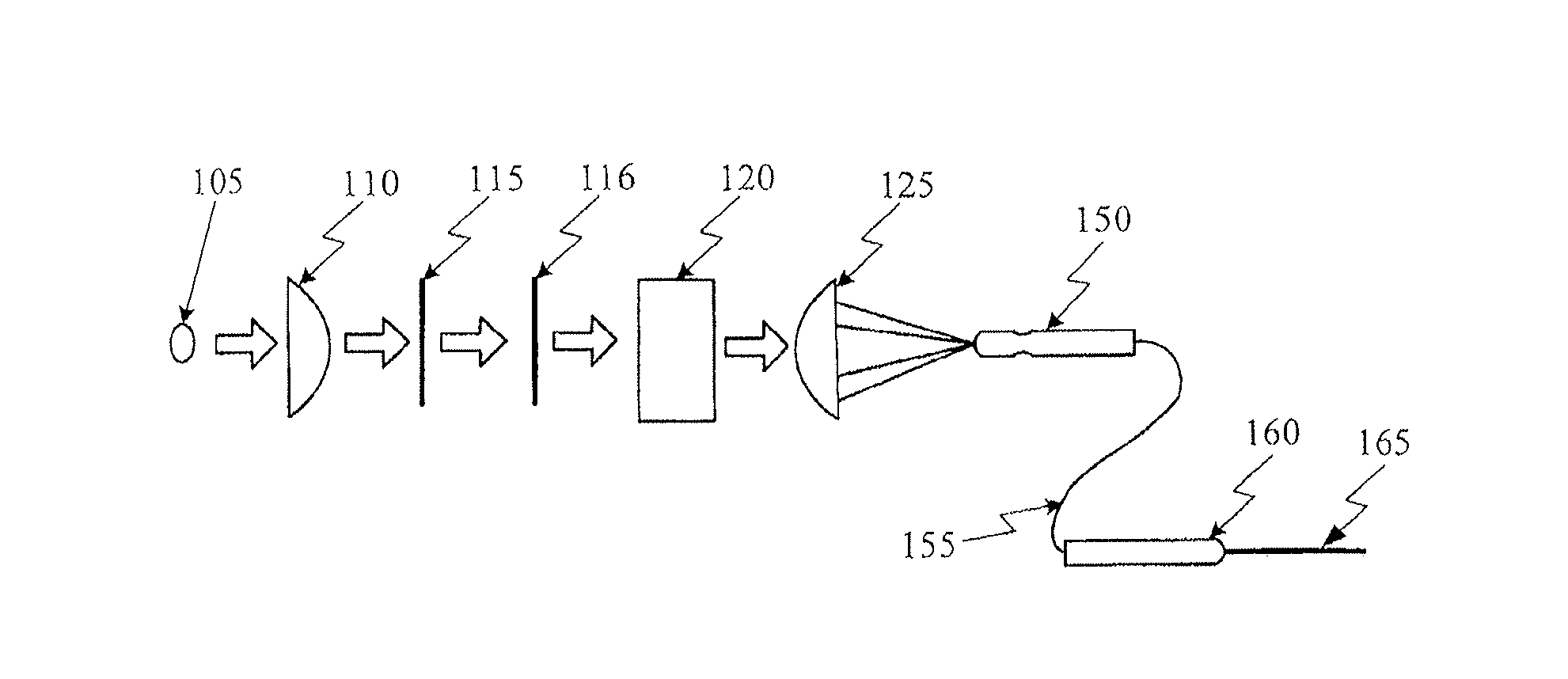
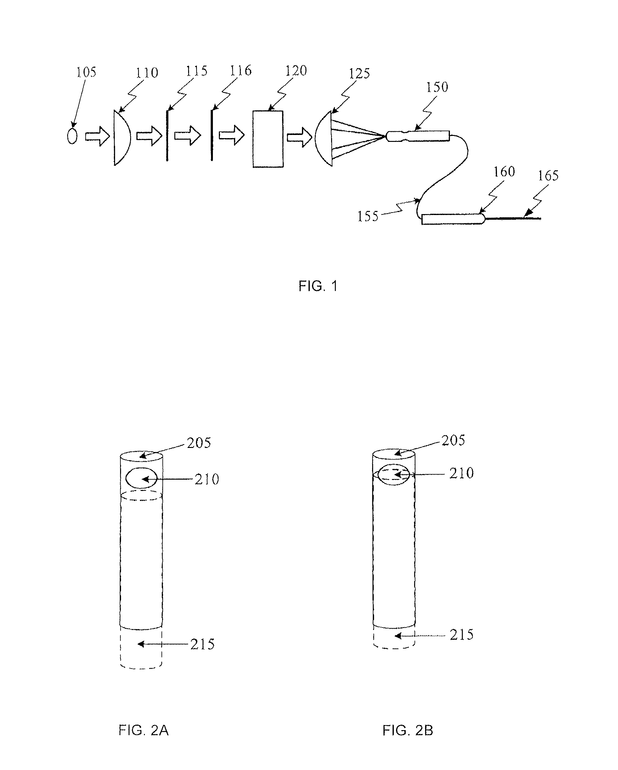
[0023]FIG. 1 is an unfolded view of an exemplary illuminated surgical instrument, such as an ophthalmic endoilluminator as used with an illuminated vitrectomy probe, according to an embodiment of the present invention. In FIG. 1, the endoilluminator includes light source 105, collimating lens 110, optional cold mirror 115, optional hot mirror 116, attenuator 120, condensing lens 125, connector 150, optical fiber 155, hand piece 160, and vitrectomy probe 165.

[0024]The light from light source 105 is collimated by collimating lens 110. The collimated light is reflected and filtered by optional cold mirror 115 and / or transmitted and filtered by optional hot mirror 116. The resulting beam is attenuated by attenuator 120 and focus...


PUM


Abstract

An illuminated surgical instrument is disclosed. One embodiment of the illuminated surgical instrument comprises a cannula and an injection-molded light-sleeve adjacent to and encircling at least a portion of the cannula. The surgical instrument can be a vitrectomy probe having a cutting port disposed at a distal end of the cannula. The light-sleeve can terminate near a distal end of the cannula, for example, near the cutting port of the vitrectomy probe. The light-sleeve is optically coupled to a light source. The light-sleeve can be injection-molded during manufacture using the cannula as an insert for the injection molding. The light-sleeve can be oriented for providing illumination in a direction along a longitudinal axis of the instrument.

Description

[0001]This application is a continuation of U.S. patent application Ser. No. 13 / 204,889 filed on Aug. 8, 2011, which claims priority under 35 U.S.C. §119 to U.S. Provisional Patent Application Ser. No. 61 / 371,882 filed on Aug. 9, 2010.BACKGROUND OF THE INVENTION[0002]The present invention relates to an illuminated surgical instrument, such as a vitrectomy probe or other illuminated ophthalmic surgical instrument, and more particularly to an illuminated surgical instrument having a molded optical light sleeve designed to provide illumination over a specific area at the working end of an instrument, for example, the cutting port of a vitrectomy probe.[0003]Anatomically, the eye is divided into two distinct parts—the anterior segment and the posterior segment. The anterior segment includes the lens and extends from the outermost layer of the cornea (the corneal endothelium) to the posterior of the lens capsule. The posterior segment includes the portion of the eye behind the lens capsu...

Claims


Application Information

Patent Timeline
Patent Type & Authority Applications(United States)
IPC IPC(8): A61F9/007A61B19/00
CPCA61B19/5202A61F9/00736A61B17/3421A61F9/00763A61B90/30B29C45/14622B29C45/14598
Inventor SCHALLER, PHILIPP
Owner ALCON INC
Learn More