
Method for locating a radio center and system for locating a radio center and data processing unit

a radio center and data processing technology, applied in the field of wireless radio communication, can solve the problems of high equipment cost, unpredictable fluctuations in radio signal strength, system cannot be used for third-party control of radio center movement, etc., and achieve the effect of reducing energy consumption, accurate localization, and reducing the frequency of measurements

Inactive Publication Date: 2013-06-06
GALOV ALEXANDER S +3
View PDF8 Cites 9 Cited by
  • Summary
  • Abstract
  • Description
  • Claims
  • Application Information

AI Technical Summary

Benefits of technology

[0040]Unexpectedly, it has discovered that, when using data on acceleration of the radio center in conjunction with the information on changes in the radio signal strength, it becomes possible to recognize linear movement of the radio center and radio center's movement with acceleration and / or speeds below a preset threshold value. This allowed overcoming the drawback of the localization method that was known from the above mentioned U.S. Pat. No. 7,042,391. Another distinctive feature of the claimed method is that the accuracy of localization is not affected by radio signal strength fluctuations, because, instead of measuring RSSI, the location is determined by the radio signal propagation time. As a result, one can use the input signal strength variation instead of absolute values of RSSI.
[0041]Simultaneous measurement of acceleration and signal strength provides accurate localization even for centers that are not equipped with instruments that measure speed or displacement. This also allows to use the system for localization of heterogeneous radio stations, some of which can be equipped only with acceleration measuring instruments (such as accelerometers) and others—only with speed and / or displacement measuring instruments (eg, speedometer, tachometer, odometer and / or frequency shift sensors).
[0042]But most importantly, it was unexpectedly discovered that, if only the minimum absolute value in the sequence of reference distances between the RCKL and a stationary radio center is used for localization calculation, all other things being equal, the time to achieve the desired localization confidence interval will be several times less than when measuring the radio signal strength. This reduces the frequency of measurements, reduces energy consumption, frees up the airwaves and increases accuracy of recording the moving object's track, as compared to the localization method described in the above-mentioned U.S. Pat. No. 7,042,391.

Problems solved by technology

The drawback of the global navigation satellite systems is that satellite signals are so weak that one cannot accurately determine the coordinates inside buildings, therefore, such a system can not be used for a third-party control of radio center movements.
The limitation of all global positioning systems is the high cost of equipment that provides accurate synchronization of all RCKL over time.
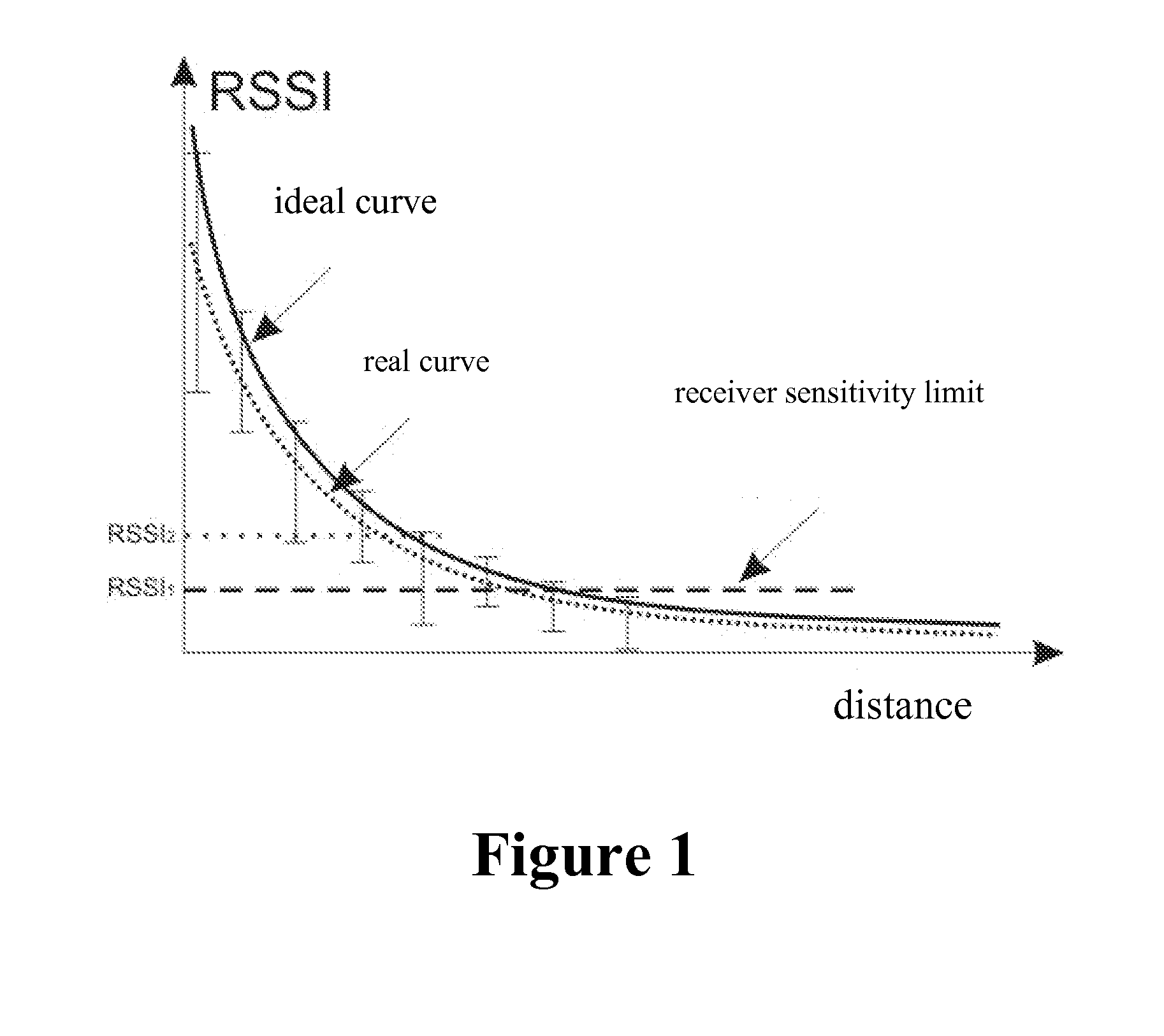
The disadvantages of methods based on measuring the RSSI are related to the fact that the measured input signal strength is strongly influenced by propagation conditions and by method of detection of radio waves, particularly by the antennas' anisotropy in the direction of the signal, by the presence and nature of radio interference (not necessarily on the same frequency), specifics of the terrain, changes of the relative location of objects in the localization zone during measurement process (especially indoors), power supply fluctuations, changes in the atmospheric conditions during measurements, rocking of the antennas etc.
(See article Eiman Elnahrawy, Xiaoyan Li, Richard P. Martin, > IEEE SECON, October 2004) The presence of these factors results in unpredictable fluctuations in the radio signal strength (see ibid.)
This disadvantage is compounded by the fact that modern equipment is characterized by inaccurate discretization of measurements and by narrow dynamic range, so it does not allow to measure the signal strength with desired accuracy.
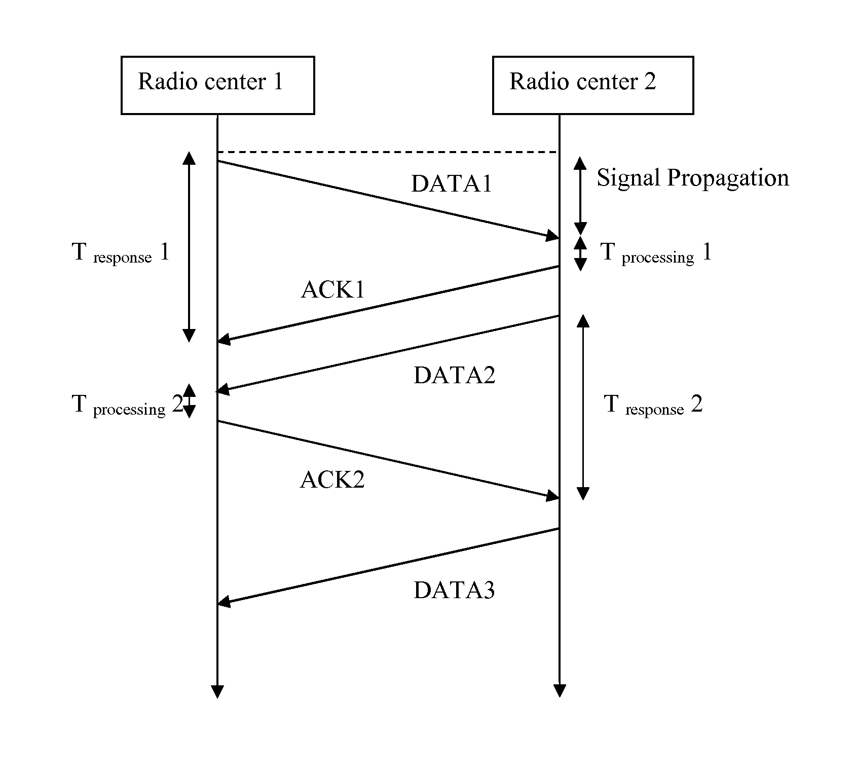
The limitation of this method is that the measurement accuracy is reduced due to the inability to compensate for the difference between speeds of clocks (clock drift) that are used by the radio centers (see the above-mentioned article by Gogolev A.).
Although the accuracy of methods using TOF (RTT, TWR, SDS-TWR) is independent of factors contributing to the aforementioned radio signal strength fluctuations, their limitation is that, due to non-linearity of signal propagation (eg., due to multiple reflections from walls or from the ground surface), the measured distances are always longer than the shortest distance between the RCKL and the radio center.
The limitation of this method is lack of precision in the existing equipment to measure the AOA.
Overestimation of measured distances between radio centers is a common problem with methods based on TOF and RSSI, the only difference being that TOF values by definition cannot be less than the shortest distance between radio centers, whereas instantaneous RSSI values can be either higher or lower than the true ones, and accuracy of distances calculation is not improved by the accumulation of instantaneous strength values (see article Elnahrawy E., Xiaoyan Li, Martin R. P. >, Sensor and Ad Hoc Communications and Networks, 2004, ISBN: 0-7803-8796-1).
The problem that prevents achieving the technical results mentioned below with this method is that it requires high-frequency measurements for each distance (about 1000 Hz), which overloads the airwaves and leads to high power consumption by the radio center.
This system is not suitable for simultaneous localization of a large number of radio centers over a long period of time without recharging.
The limitation of these systems that prevents achieving the technical result mentioned below is that they require time and labor consuming preliminary calibration.
The disadvantage of this method that prevents achieving the technical result mentioned below is that, due to strength fluctuations, the strong signal does not always mean that the radio center is actually in the line of sight of the RCKL.
Another limitation that prevents achieving the technical result mentioned below is that the measurement of distances by TOF method in the conditions of the direct line of sight does not preclude overstating the results due to the radio signal reflection.
The disadvantage of these methods that prevents achieving the technical result mentioned below is in the fact that they do not account for the strength fluctuations caused by changes in the relative location of objects within the localization zone.
Another problem with these methods that prevents achieving the technical result mentioned below is labor intensity of preparing these maps.
The disadvantage of this method that prevents achieving the technical result mentioned below is that the averaged results of a small number of serial measurements are strongly influenced by fluctuations.
The common problem of the aforementioned third group of methods, which prevents achieving the technical result mentioned below, is that with vibrations, as well as with steady and rectilinear motion of the radio center, the use of data about acceleration causes serious errors in the localization.
Thus, the known methods do not ensure radio center localization with accuracy of 1 to 3 meters in conditions of considerable screening of the radio signal, in conditions of non-linear signal propagation, and / or when relative positions of objects in the area of localization are changing.

Method used


Image

  • Method for locating a radio center and system for locating a radio center and data processing unit
  • Method for locating a radio center and system for locating a radio center and data processing unit
  • Method for locating a radio center and system for locating a radio center and data processing unit

Examples


example 2

[0153]Radio center localization system, as shown in FIG. 11, works as follows.

[0154]the RCKL (3) and radio centers measure radio signal propagation time using the TM and one of the TOF methods. Using the known radio signal propagation time and TM (14), the distance between the radio center and RCKL (3) is calculated. The overlapping area is calculated for the circles with centers in the RCKL (3) and radii equal to the calculated distance; then, the localization precision is calculated according to a predetermined by the TM (10) correlation. Possible locations of the radio center are calculated taking into account the distances computed by the LC (20). Possible displacement of the radio center is calculated using the MC (9), given its preset speed limit and the length of time between successive localization points. Parameters of the object's motion are calculated by MMPR (7) (eg, magnetometer, accelerometer, speedometer, odometer, tachometer). Radio signal strength from the said radi...

example 3

[0156]FIG. 4 clearly shows how the accumulation of localization points of an immobile radio center can improve accuracy. Black dots indicate points, whose location is known in advance (A, B and C), circle number 1 is the estimated location of the mobile center after the first cycle of measurements (in the area of the overlap of all three circles), circle number 2 is the corrected location of the mobile center after adjusting the radius from center A (the corrected radius is shown by the dashed line).

[0157]When speed and / or acceleration of the radio center and change of the radio signal strength are below the threshold, the minimum value is selected (R+dR)min from a series of consecutive values for each pair—radio station / RCKL:

R+dR1,R+dR2, . . . ,R+dRn,

[0158]where dRi is the overestimation of the i-th measurement of the true distance R

[0159]of the measured distances between the radio center and the RCKL for the radio center immobility period. Since the true distance between the immob...

example 4

[0161]In one particular case of implementation, the presented method is used with the system containing radio centers, RCKL and the controls and data processing equipment (CDPE), as shown in FIG. 6, where positions 1-6 indicate the following: controls server, switching, data acquisition and processing (1), the switch (2), RCKL (3), radio center (4), the World Wide Web (5) and coverage area of RCKL (6).

[0162]Radio centers may occasionally leave the state of low power consumption and transmit a radio signal that is received by many RCKL, which cover the area where the radio center is located. RCKL are connected into a single information environment through wired or wireless telecommunications network. Radio signals' data is transmitted over the said network to the said CDPE.

[0163]CDPE selects a RCKL and starts the process of distances measurement by the presented method using the selected RCKLs (applicable for the radio center in question). During this, the first radio center comes ou...


PUM


Abstract

The present invention group is related to wireless radio communication and, in particular, to devices and methods for determining the location (position) of a radio center relative to radio centers with known location. A method and a system for locating a radio center are proposed, as well as data processing unit that allows to improve the accuracy of localization by selecting minimum distance values as measured by the radio signal propagation time for the entire period of immobility of the radio center. The technical result consists of the increase of the immunity of the localization method, reducing the duration of measuring period, the possibility of locating radio centers that are heterogeneous in terms of the method being used for determining their motion.

Description

TECHNICAL FIELD OF THE INVENTION[0001]The present invention group relates to wireless radio communication and, in particular, to devices and methods for determining the location (position) of a radio center relative to radio centers with known location (hereinafter—“RCKL”).TECHNICAL BACKGROUND[0002]There are global navigation satellite systems (GNSS), for example, GPS and GLONASS. Location is determined based on measuring the delay of a short radio pulse propagation from the moment it is sent by a RCKL (ie. by a satellite) and until it is received by the radio center. Knowing the propagation delay (further—TOF, or Time of Flight), one can calculate the distance between them. Ideally, to determine the three-dimensional location of a mobile object, four RCKL will be needed. The drawback of the global navigation satellite systems is that satellite signals are so weak that one cannot accurately determine the coordinates inside buildings, therefore, such a system can not be used for a th...

Claims


Application Information

Patent Timeline
Patent Type & Authority Applications(United States)
IPC IPC(8): G01S5/08
CPCG01S5/08G01S5/14
Inventor GALOV, ALEXANDER S.GORDEEV, DENIS E.MOSHCHEVIKIN, ALEXEY P.SOLOVYEV, ALEXEY V.
Owner GALOV ALEXANDER S
Learn More