
Multicore Optical Fiber with Reduced Inter-Core Crosstalk

inter-core crosstalk technology, applied in the direction of cladded optical fibre, instruments, optical elements, etc., can solve the problems of weak and unstable mode coupling, high cost, complex and expensive transceivers at the endpoints of such links, and the ultimate channel capacity may be severely compromised, so as to reduce inter-core crosstalk and reduce inter-core crosstalk in a multi-core optical fiber

Active Publication Date: 2013-05-30
AT&T INTPROP I L P
View PDF3 Cites 51 Cited by
  • Summary
  • Abstract
  • Description
  • Claims
  • Application Information

AI Technical Summary

Benefits of technology

The present disclosure describes ways to reduce interference between optical signals in a multi-core optical fiber. This can be achieved by transmitting signals in different cores of the fiber at different velocities. This design helps to minimize inter-channel crosstalk, which can lead to improved performance and reliability in optical communication systems.

Problems solved by technology

Each transverse mode has a characteristic pattern of light distribution across the core and light is easily coupled from one mode to another, leading to a complex situation when light must be launched from a laser or extracted for a receiver.
Although one can conceive of SDM transmission across a conventional multimode fiber, this approach can lead to strong and unstable mode coupling, with energy transferred from mode to mode as the fiber bends or shifts with time.
In this case, the transceivers at the endpoints of such links would have to be quite complex and expensive, because the transceivers would be required to sort out the fluctuating energy transfer, which is a very computation-intensive process.
For certain coupling coefficients, the ultimate channel capacity may be severely compromised by the mode coupling.
In addition, all-optical add / drop of individual modes from such strongly-coupled channels is problematic, requiring optical mode coupling compensators which are not currently available.
Further, it is likely that different spatial modes in a multimode fiber will need to have their powers rebalanced along a long transmission path, and this rebalancing will be very difficult when the modes are strongly mixed.
However, at 1490 nm, core-to-core crosstalk introduces significant system penalties, and the data suggests that in the C-band near 1550 nm, such penalties would be severe.

Method used


Image

  • Multicore Optical Fiber with Reduced Inter-Core Crosstalk
  • Multicore Optical Fiber with Reduced Inter-Core Crosstalk
  • Multicore Optical Fiber with Reduced Inter-Core Crosstalk

Examples


Embodiment Construction

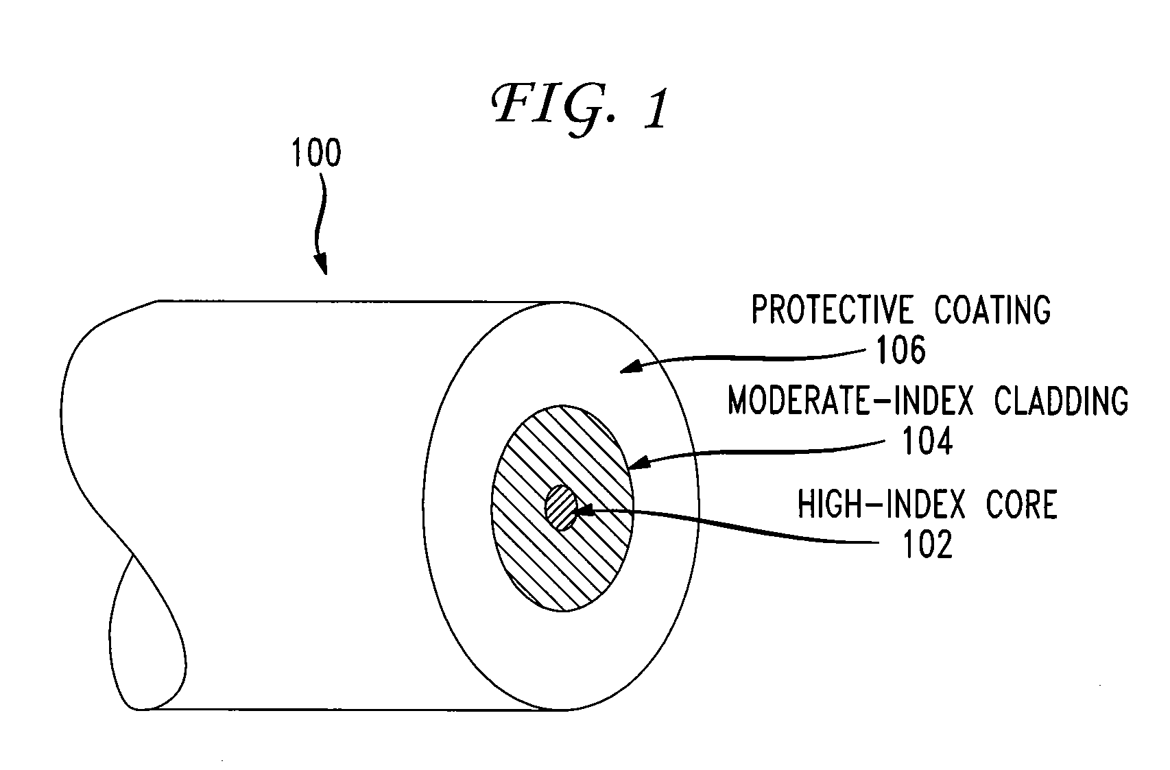
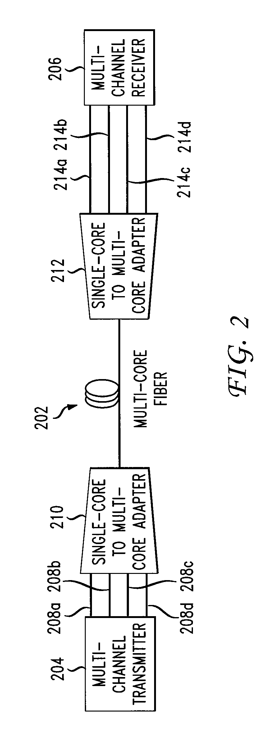
[0020]A multicore fiber is an optical fiber having multiple separate cores embedded in a cladding region, and each core provides a separate spatial mode for propagating optical signals. FIG. 2 illustrates a communication system using a multicore fiber. As illustrated in FIG. 2, a multicore optical fiber 202 is connected between multi-channel transmitter 204 and a multi-channel receiver 206. It is to be understood that the multi-channel transmitter 204 and the multi-channel receiver 206 can both be implemented using a transceiver capable of transmitting and receiving optical signals. The multi-channel transmitter 204 may receive multiple data signals. For example, the data signals may be electrical signals representing streaming data. The multi-channel transmitter 204 can divide each data signal into multiple subsignals, modulate the subsignals of a data signal onto optical carrier waves having different wavelengths, and multiplex the resulting optical subsignals for each data signal...


PUM


Abstract

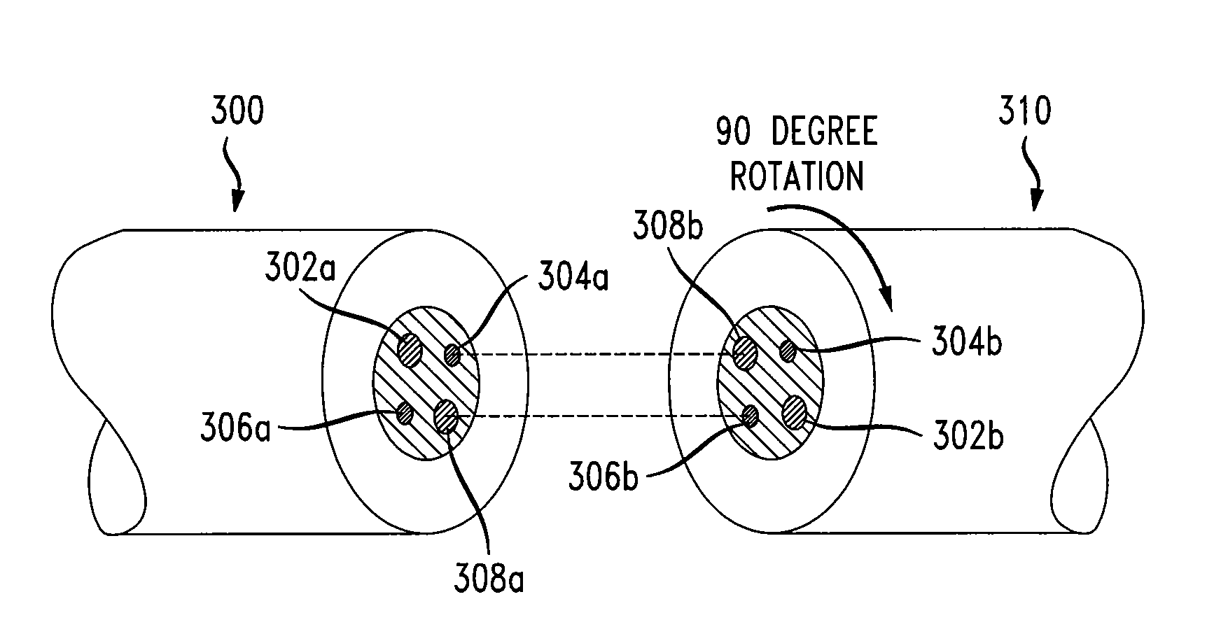
Various apparatus and methods for reducing inter-core crosstalk in a multicore optical fiber are disclosed. A multicore optical fiber may include a plurality of cores capable of transmitting optical signals, and a cladding surrounding the cores, the cladding having a heterogeneous refractive index such that the optical signals propagate at different velocities in different ones of the cores. A multicore optical fiber may include a first length including cores having heterogeneous modal velocities and a second length, adjacent to the first length, including cores having heterogeneous modal velocities, and the cores in the first length are aligned with cores in the second length having a different modal velocity. Inter-core cross talk in a multicore optical fiber may also be reduced by transmitting optical signals through cores of a multicore optical fiber and pumping light into the cores to create unequal modal velocities in the cores.

Description

FIELD[0001]The present disclosure relates to transmission of data over optical fibers, and in particular relates to reducing inter-core crosstalk in a multicore optical fiber.BACKGROUND[0002]In fiber-optic communication system development, increasing the capacity of a fiber transport connection has been a continuing goal. In early optical communications systems virtually all transport was implemented by On-Off Keying (OOK) of a single wavelength, and throughput was upgraded by increasing the symbol rate. This was followed by the introduction of parallelization into the fiber link by carrying many different data streams on separate wavelengths in the same optical fiber using wavelength-division multiplexing (WDM). Currently, wavelength counts in practical deployments have coalesced around 80-96 wavelengths per fiber at 50 GHz spacing, and have stopped increasing rapidly. Other sophisticated modulation formats being used in evolving fiber optic communication systems include Polarizati...

Claims


Application Information

Patent Timeline
IPC IPC(8): G02B6/02G02B6/028
CPCG02B6/02042H04B10/2916H04B10/2581H04J14/04H04J14/02H04J14/052
Inventor FEUER, MARK D.
Owner AT&T INTPROP I L P
Learn More