Touch sensor

a technology of touch sensor and sensor, which is applied in the field of touch sensor, can solve the problems of large installation area, inability to distinguish the power-on switch from the other operators, and inability to reliably manipulate the manipulation button smoothly, and achieves the effect of convenient continuous operation, convenient menu selection, and smooth manipulation of the manipulation button

Active Publication Date: 2013-05-30
U SHIN LTD
View PDF3 Cites 11 Cited by
  • Summary
  • Abstract
  • Description
  • Claims
  • Application Information

AI Technical Summary

Benefits of technology

[0016]According to the third aspect of the present invention, the provision of the switch as well as the touch sensor makes the menu selection easier. In addition, since the multiple electrodes are arranged in the arc shape along the manipulation button of the switch, the arrangement makes it easier to continuously operate any one of the electrodes by following the manipulation of the manipulation button. For example, in a case where the touch sensor is installed on the steering wheel, the driver manipulates the touch sensor while holding the steering wheel. To this end, the touch sensor can be arranged within a reach of the thumb of the driver which is a manipulating finger. This arrangement enables the driver to smoothly manipulate the manipulation button of the switch and the touch sensor without releasing the h

Problems solved by technology

However, in the structure proposed in Japanese Patent Application Publication No. 2003-131760, a power key for activating the touch sensor and a release key for selecting an operation mode are provided separately, and thus a large area is required to install these switches.
In addition, without looking at the switches, an operator cannot distinguish the power-on switch from the others.
For these reasons, the sensor is inevitably large in size, and complicated manipulation imposes larger burden on the operator.
These cause

Method used


Image

  • Touch sensor
  • Touch sensor
  • Touch sensor

Examples


Embodiment Construction

[0025]An embodiment of the present invention will be described below based on the attached drawings.

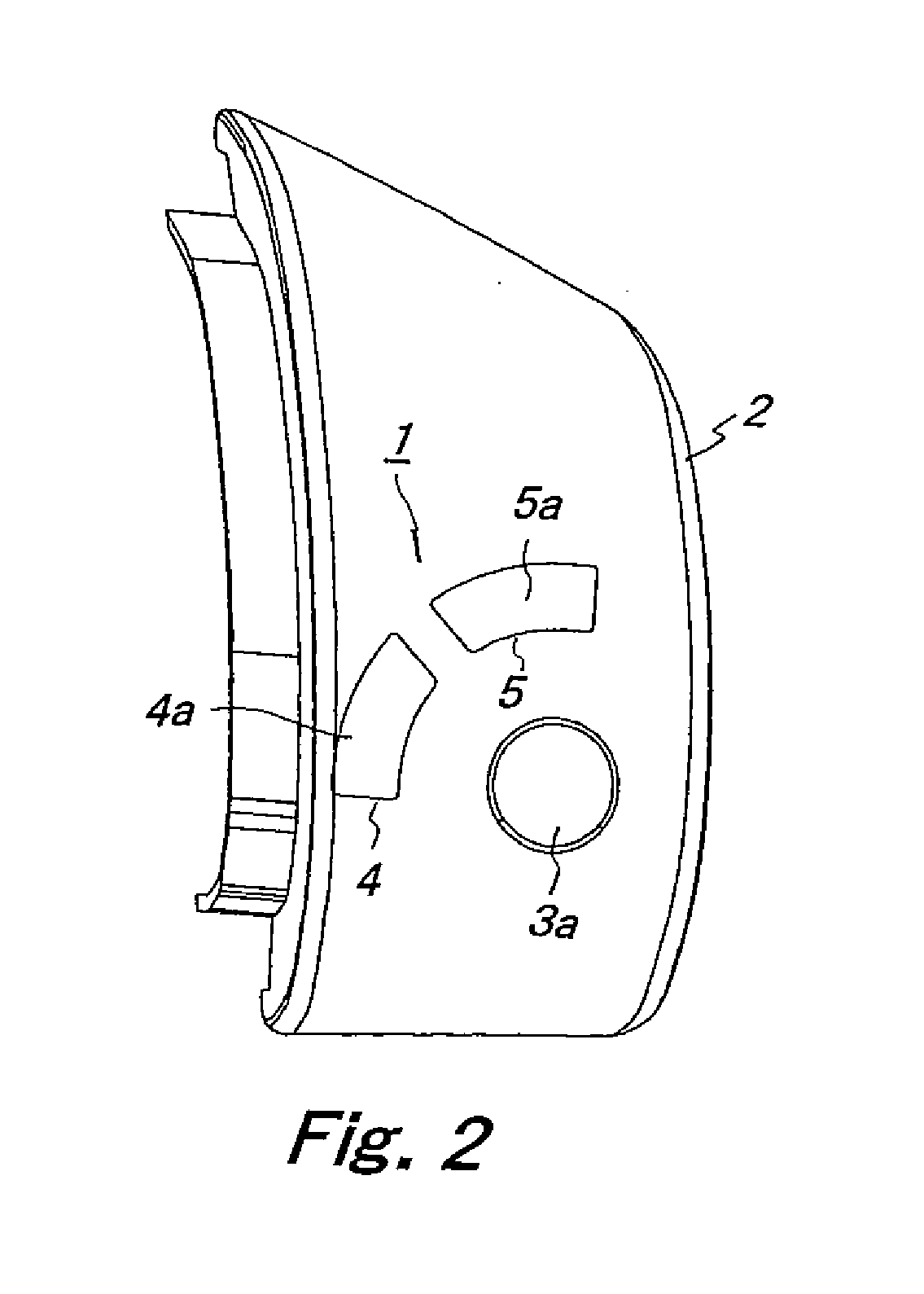
[0026]FIG. 1 is a front view of a steering wheel on which a touch sensor according to the present invention is installed; FIG. 2 a front view of the touch sensor; and FIG. 3 is a back view of the touch sensor. In this embodiment, the touch sensor 1 is installed on a steering wheel 50 of a vehicle with a case2 placed in between, as shown in FIG. 1.

[0027]As shown in FIG. 3, a mode selection switch 3 which is a mechanical push switch and two electrodes A, B are arranged on the back side of the case 2. As shown in FIG. 2, a circular manipulation button 3a of the mode selection switch 3 is exposed to the outside from a surface of the case 2. As shown in FIG. 2, touch manipulation parts 4, 5 leading to the respective electrodes A, B are arranged on the surface of the case 2 in an arc shape along an outer periphery of the manipulation button 3a. Here, the mode selection switch 3 is a switch ...


PUM


Abstract

Provided is a touch sensor having a simple structure and enabling a driver to appropriately and quickly manipulate the touch sensor as intended without looking at a manipulation surface of the touch sensor. The touch sensor includes: multiple electrodes; detection means for detecting touch on any of electrodes and for outputting a detection signal for each electrode; touch judgment means for judging whether each of the electrodes is touched or untouched based on the detection signal; a switch having a manipulation button; control mode judgment means for determining a control function for a controlled device in accordance with an input signal transmitted from the switch when the manipulation button is manipulated; and permission means for permitting the touch judgment means to judge touch on each electrode in response to the input signal from the switch.

Description

BACKGROUND OF THE INVENTION[0001]1. Field of the Invention[0002]The present invention relates to a touch sensor configured to detect a user's touch on an electrode based on a change in the capacitance of the electrode.[0003]2. Description of the Related Art Japanese Patent Application Publication No. 2003-131760, for example, has proposed a structure to control various devices of a vehicle such as an air conditioner and an audio system by using a capacitive touch sensor. The structure is configured to read the trace of movement of a finger of an operator by using the touch sensor; judge which manipulation pattern the trace matches; and control the various devices based on an operation instruction matching the manipulation pattern.SUMMARY OF THE INVENTION[0004]However, in the structure proposed in Japanese Patent Application Publication No. 2003-131760, a power key for activating the touch sensor and a release key for selecting an operation mode are provided separately, and thus a la...

Claims


Application Information

Patent Timeline
IPC IPC(8): H03K17/96
CPCH03K17/96H03K2217/96073H03K2017/9602H03K17/962
Inventor FUKUSHIMA, KAZUYUKIKAWASE, TOMOTOKUDOME, TETSUO
Owner U SHIN LTD
Why Eureka
Try Eureka