Direct drive wind turbine and method for controlling an air gap

a direct drive, wind turbine technology, applied in the direction of electric generator control, machines/engines, mechanical equipment, etc., can solve the problems of not being able to control the air gap between the generator rotor and the generator stator, the rotation of the generator shaft is very slow, and the need for a large and relatively expensive generator is generally large, so as to reduce the transmission of bending loads to the generator rotor, the design is lighter, and the effect of easy control

Active Publication Date: 2013-05-30
GE RENEWABLE TECH WIND BV
View PDF12 Cites 9 Cited by
  • Summary
  • Abstract
  • Description
  • Claims
  • Application Information

AI Technical Summary

Benefits of technology

[0009]In a first aspect, the present invention provides a direct drive wind turbine comprising a rotor and a generator, the rotor comprising a hub and a plurality of blades and being rotatably mounted on a frame, and the generator comprising a generator rotor and a generator stator, further comprising one or more dampers arranged between the rotor and the generator rotor and extending at least partially in an axial direction. Because of the rotor being rotatably mounted on a frame, the transmission of bending loads to the generator rotor may be reduced, thus making it easier to control the air gap. Additionally, the generator rotor may have a lighter design since the loads that it has to support may be reduced. And by providing a damper that at least partially dissipates the energy of a bending movement of the hub, the resulting movement or deformation of a generator rotor may be reduced. In this sense, the axial direction is defined by the axis of rotation of the rotor (which would normally correspond to the axis of rotation of the generator rotor).

Problems solved by technology

However, since there is no speed increase, the generator shaft rotates very slowly.
As a consequence, a large and relatively expensive generator is generally needed to be able to generate electricity in an effective way.
Additionally, when bending loads and movements (and corresponding deformations) are transmitted through the rotor shaft to the generator, it may not be possible to control the air gap between generator rotor and generator stator.
High bending loads can even cause structural damage to parts of the generator, e.g. its bearings.
Replacement or repair of such generator parts may be very expensive due to the size and related cost of the generator and its components.
This may represent an improvement with respect to other prior art wind turbines, but the transmission of bending loads from the rotor to the generator cannot be avoided entirely.

Method used


Image

  • Direct drive wind turbine and method for controlling an air gap
  • Direct drive wind turbine and method for controlling an air gap
  • Direct drive wind turbine and method for controlling an air gap

Examples


Embodiment Construction

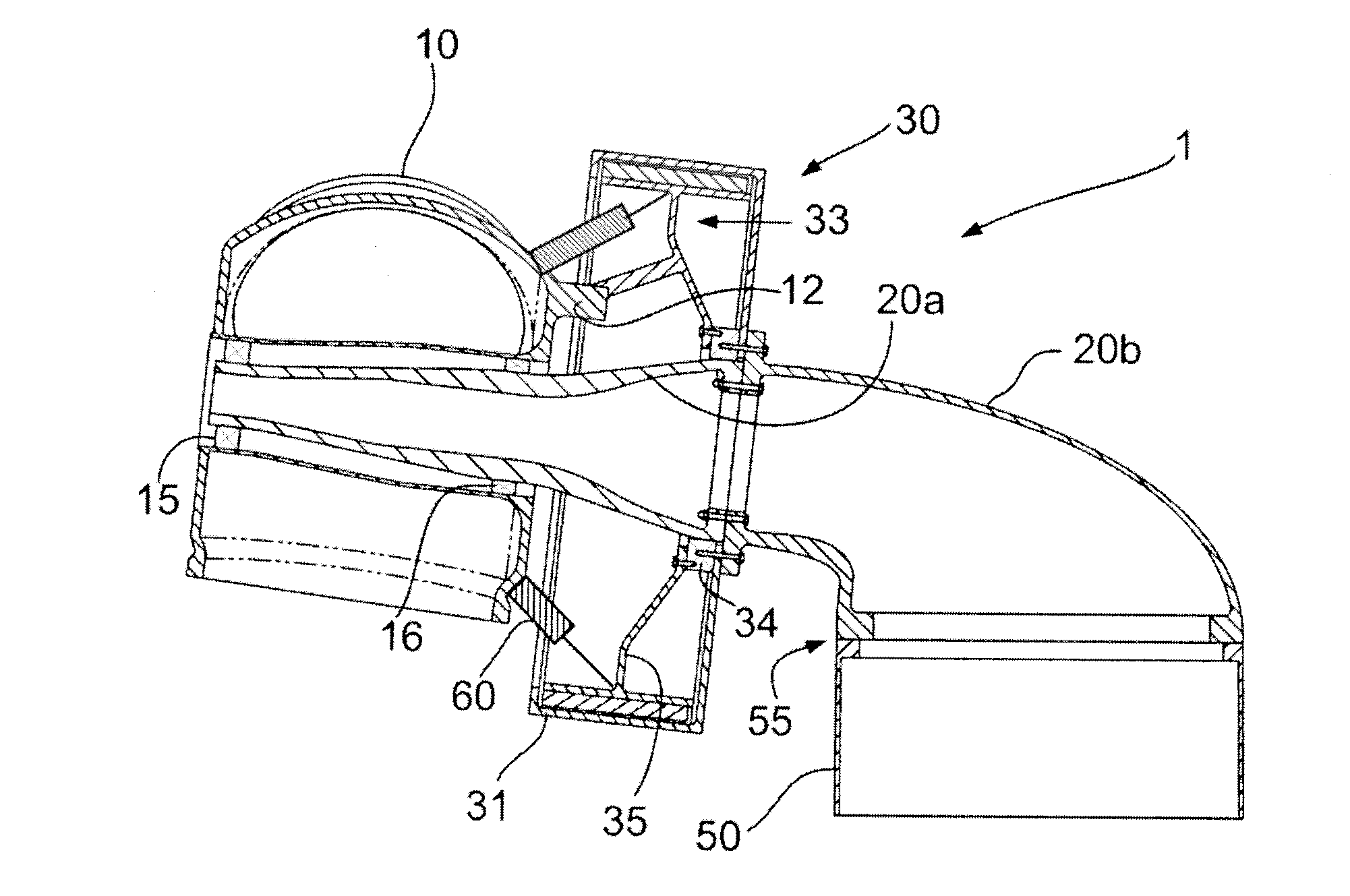
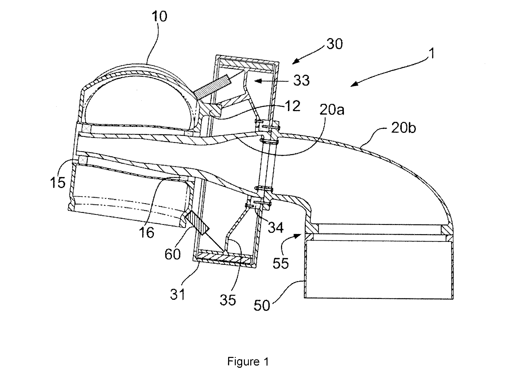
[0024]FIG. 1 illustrates a first embodiment of a wind turbine 1 according to the present invention. Wind turbine 1 comprises a tower 50 upon which a frame 20 is rotatably mounted. In this embodiment, frame 20 comprises two separate sections: a front frame 20a and a rear frame 20b. Reference sign 55 indicates the presence of a yaw mechanism, which allows rear frame 20b to be rotated around the longitudinal axis of the wind turbine tower. Rear frame 20b and front frame 20a may comprise inward annular flanges. In the embodiment shown, bolts are used to connect these flanges.

[0025]Rotor hub 10 is rotatably mounted on front frame 20a through bearings 15 and 16. Rotor hub 10 carries a plurality of blades (not shown). A generator 30 is also mounted on frame 20. Generator housing 31 is connected through bolts to an annular flange provided on rear frame 20b. Schematically indicated with reference sign 34 is a suitable bearing, rotatably supporting a generator rotor 33. Any suitable bearing m...


PUM


Abstract

A direct drive wind turbine comprising a rotor and a generator, the rotor comprising a hub and a plurality of blades and being rotatably mounted on a frame, and the generator comprising a generator rotor and a generator stator, further comprising one or more dampers arranged between the rotor and the generator rotor and extending at least partially in an axial direction.

Description

[0001]Direct drive wind turbine and method for controlling an air gap[0002]The present invention relates to a wind turbine, and more particularly to a direct drive wind turbine. The present invention furthermore relates to a method for controlling an air gap, and more particularly to such a method in a direct drive wind turbine.BACKGROUND ART[0003]Modern wind turbines are commonly used to supply electricity into the electrical grid. Wind turbines of this kind generally comprise a rotor with a rotor hub and a plurality of blades. The rotor is set into rotation under the influence of the wind on the blades. The rotation of the rotor shaft drives the generator rotor either directly (“directly driven”) or through the use of a gearbox. Direct driven wind turbines also may be “shaftless”; in these shaftless wind turbines, the rotor directly drives the generator.[0004]Direct drive wind turbines such as known from e.g. WO 2005 / 103489, do not suffer from known problems related to the gearbox...

Claims


Application Information

Patent Timeline
Patent Type & Authority Applications(United States)
IPC IPC(8): F03D7/02F03D9/00
CPCF03D11/028F05B2260/96Y02E10/722F03D9/002F03D7/0296F03D9/25F03D15/20F03D80/70Y02E10/72
Inventor RODRIGUEZ TSOUROUKDISSIAN, ARTURO
Owner GE RENEWABLE TECH WIND BV
Why Eureka
Try Eureka