
Dual downhole pressure barrier with communication to verify

a technology of communication and verification, applied in the direction of survey, borehole/well accessories, construction, etc., can solve the problems of large platform, large carrying capacity of large vessels, and high operating expenses of drilling rigs that drill wells,

Inactive Publication Date: 2013-05-30
TEJAS RES & ENG
View PDF5 Cites 54 Cited by
  • Summary
  • Abstract
  • Description
  • Claims
  • Application Information

AI Technical Summary

Benefits of technology

This patent describes a system that allows pressure data to be collected from deep wells and transmitted to the surface wirelessly. The system includes a device called an intelligent well suspension plug, which is placed at the bottom of the well and can communicate data to the surface. This system can be deployed along with other tools, such as a liner or sand control screen, using a single trip into the well. A separable work string can also be used for running these tools into the well. The technical effect of this patent is improved deep well pressure monitoring and data transmission without the need for hardwiring or costly equipment.

Problems solved by technology

The drilling of wells in deep water requires large vessels with very large carrying capacity and large platforms for storage of materials and equipment.
This means very high operating expenses for the drilling rigs that drill the wells.

Method used


Image

  • Dual downhole pressure barrier with communication to verify
  • Dual downhole pressure barrier with communication to verify
  • Dual downhole pressure barrier with communication to verify

Examples


Embodiment Construction

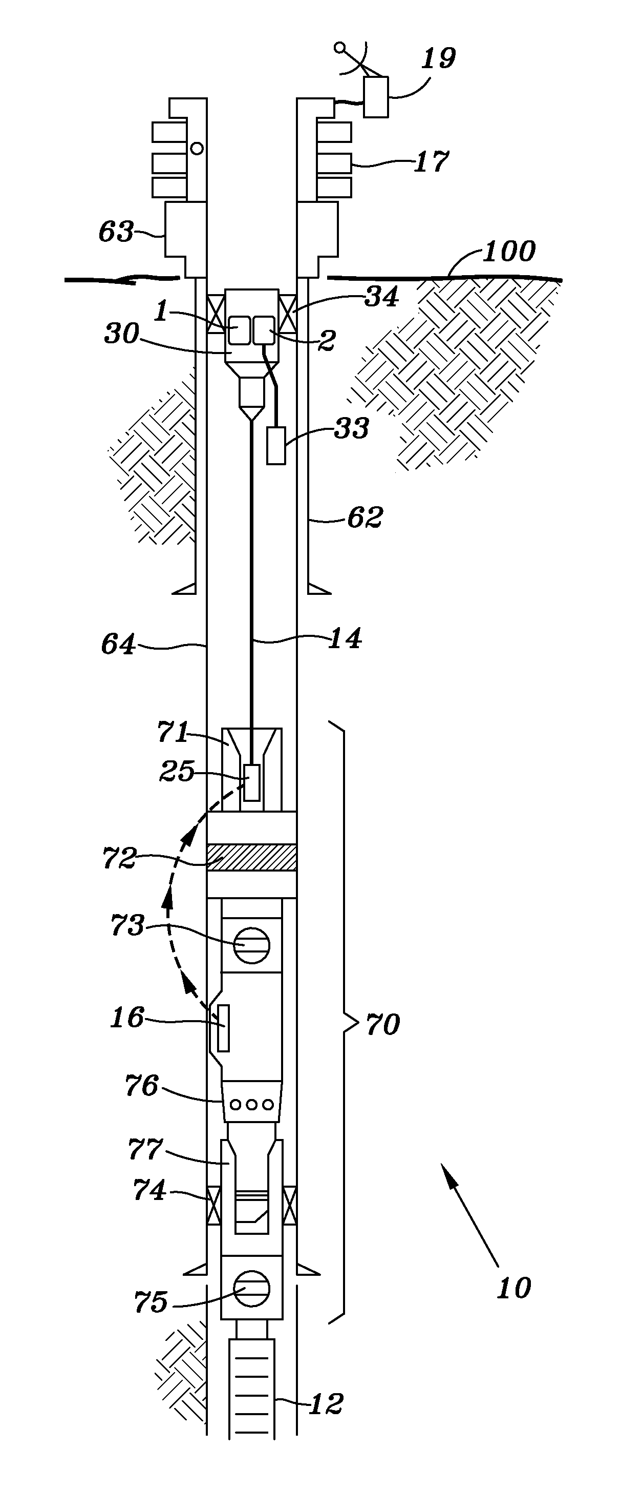
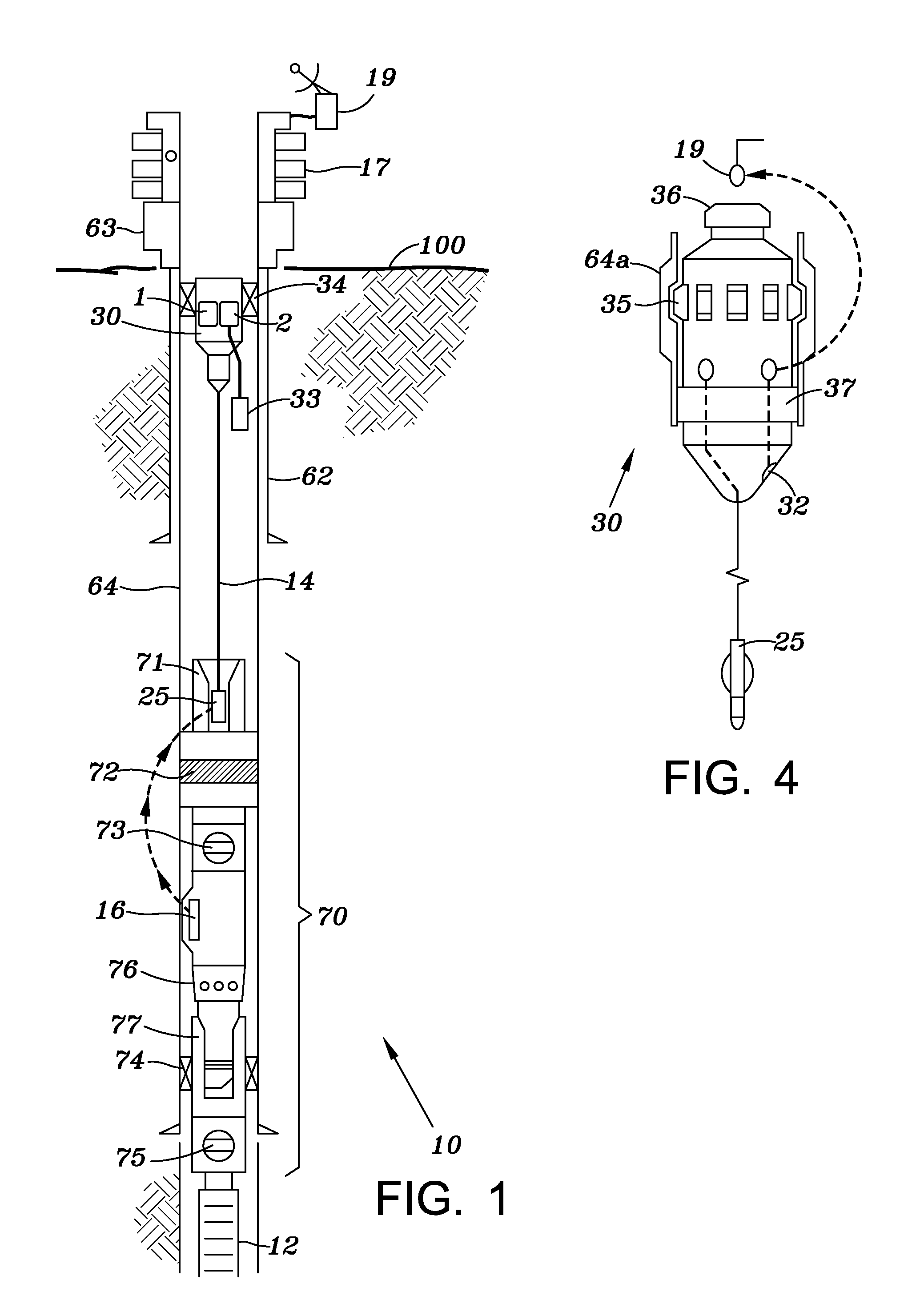
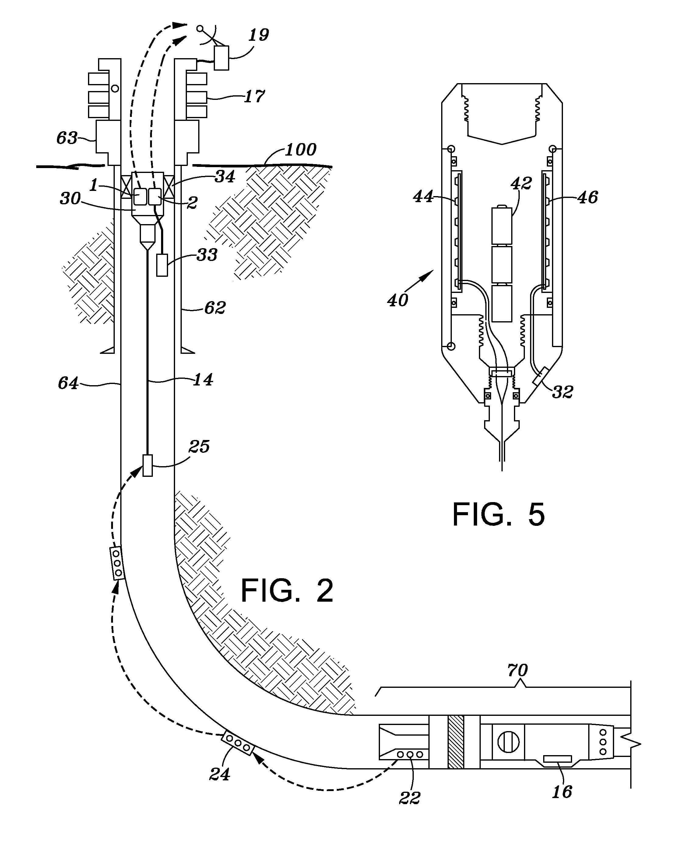
[0025]Referring to FIG. 1, vertical (or substantially vertical) well 10, drilled below seafloor 100, is illustrated equipped with one embodiment of Dual Downhole Barrier System (DDBS) 70. “Substantially vertical” means that probe 25, suspended by cable 14, will move along the inside surface of casing 64 by gravity to be placed near enough to telemetry sub 16 to establish communication, by electromagnetic pulses or other means, between the probe and the sub. In the figures and in the description, “below” means a greater distance in the well from the top of the well. In the embodiment shown, telemetry sub 16 also includes a P / T (pressure and temperature) sensor, which is located between the downhole barriers. Alternatively, sensors that are located below lower or primary barrier valve 75 may be separately provided and in communication with sub 16. Such an embodiment would allow for three or more pressure or pressure / temperature measurements to be sent to the surface. Only two signals ...


PUM


Abstract

Apparatus and method are provided for placing a dual pressure barrier in a vertical or horizontal well and verifying by pressure sensors in the well that the pressure barriers are operable. Communication of data from the well may be by electromagnetic or acoustic signals, and the data may be acquired on a ship near the well.

Description

[0001]This application claims priority to Provisional Application Ser. No. 61 / 683,749 filed on Aug. 16, 2012 and Provisional Application Ser. No. 61 / 701,317 filed on Sep. 14, 2012.BACKGROUND OF INVENTION[0002]1. Field of the Invention[0003]This application is directed to drilling and completion of wells subsea. More particularly, apparatus and method are provided for decreasing the risk of hydrocarbons flowing from a well after it is drilled and as the well is completed for production.[0004]2. Description of Related Art[0005]Operations for recovering hydrocarbons from beneath the sea have expanded to many areas of the world and to ever deeper water. The drilling of wells in deep water requires large vessels with very large carrying capacity and large platforms for storage of materials and equipment. This means very high operating expenses for the drilling rigs that drill the wells. After a well is drilled subsea, the well must be “completed,” which means placing equipment in the wel...

Claims


Application Information

Patent Timeline
Patent Type & Authority Applications(United States)
IPC IPC(8): E21B47/06
CPCE21B33/10E21B47/06E21B47/122E21B47/13
Inventor HILL, JR., THOMAS G.
Owner TEJAS RES & ENG
Learn More