
Modular prosthetic sockets and methods for making same

a technology of prosthetic sockets and modules, applied in the field of prosthetic sockets, can solve the problems of less than satisfactory aspects of the process, the degree of possible modification of the limb socket to optimize the fit of the residual limb socket is actually quite limited, and the use of the distal components can be severely compromised, so as to improve the biomechanically appropriateness of the dimensions or contours, and improve the fit of the sock

Active Publication Date: 2013-05-16
LIM INNOVATIONS
View PDF1 Cites 86 Cited by
  • Summary
  • Abstract
  • Description
  • Claims
  • Application Information

AI Technical Summary

Benefits of technology

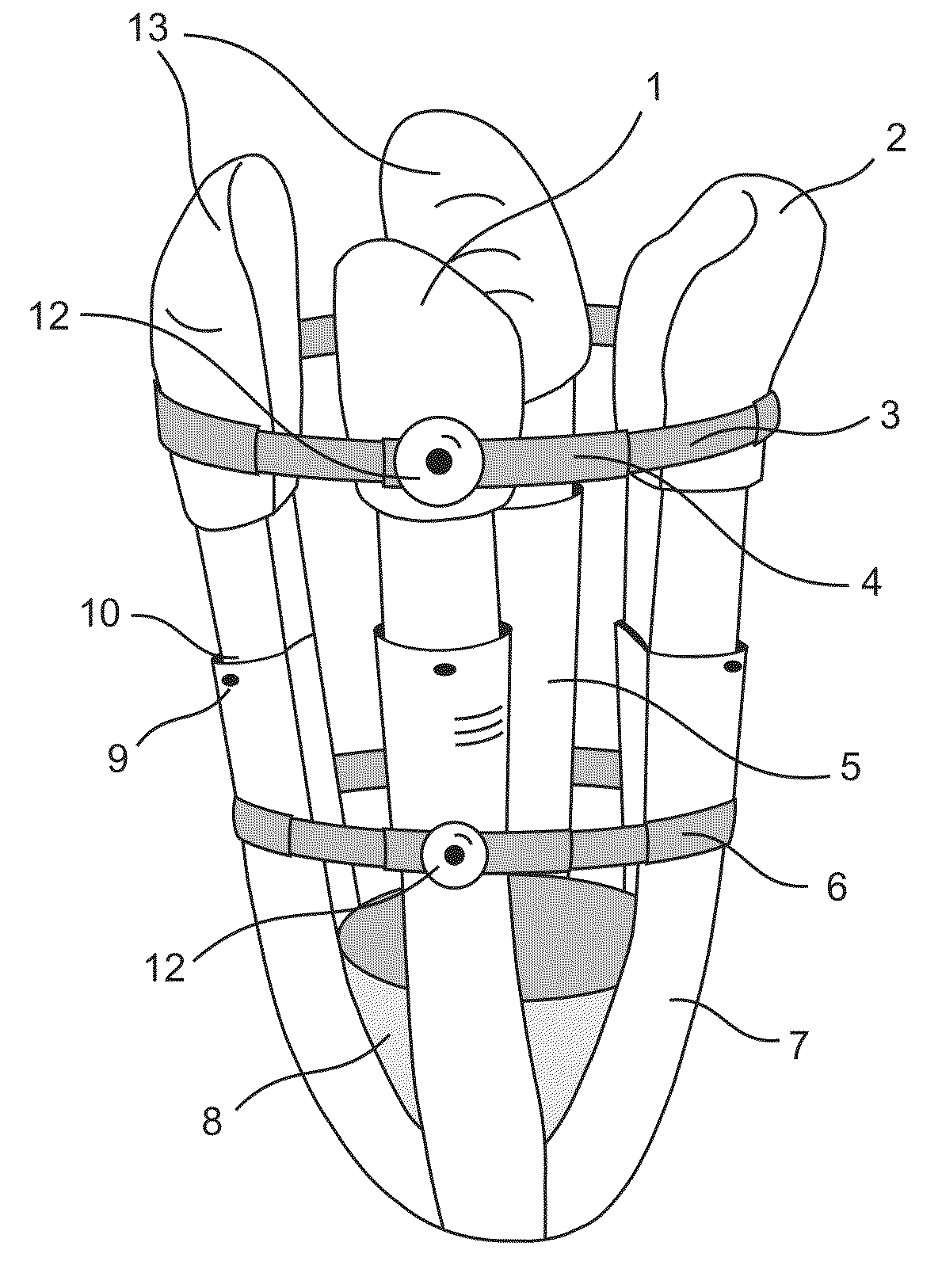
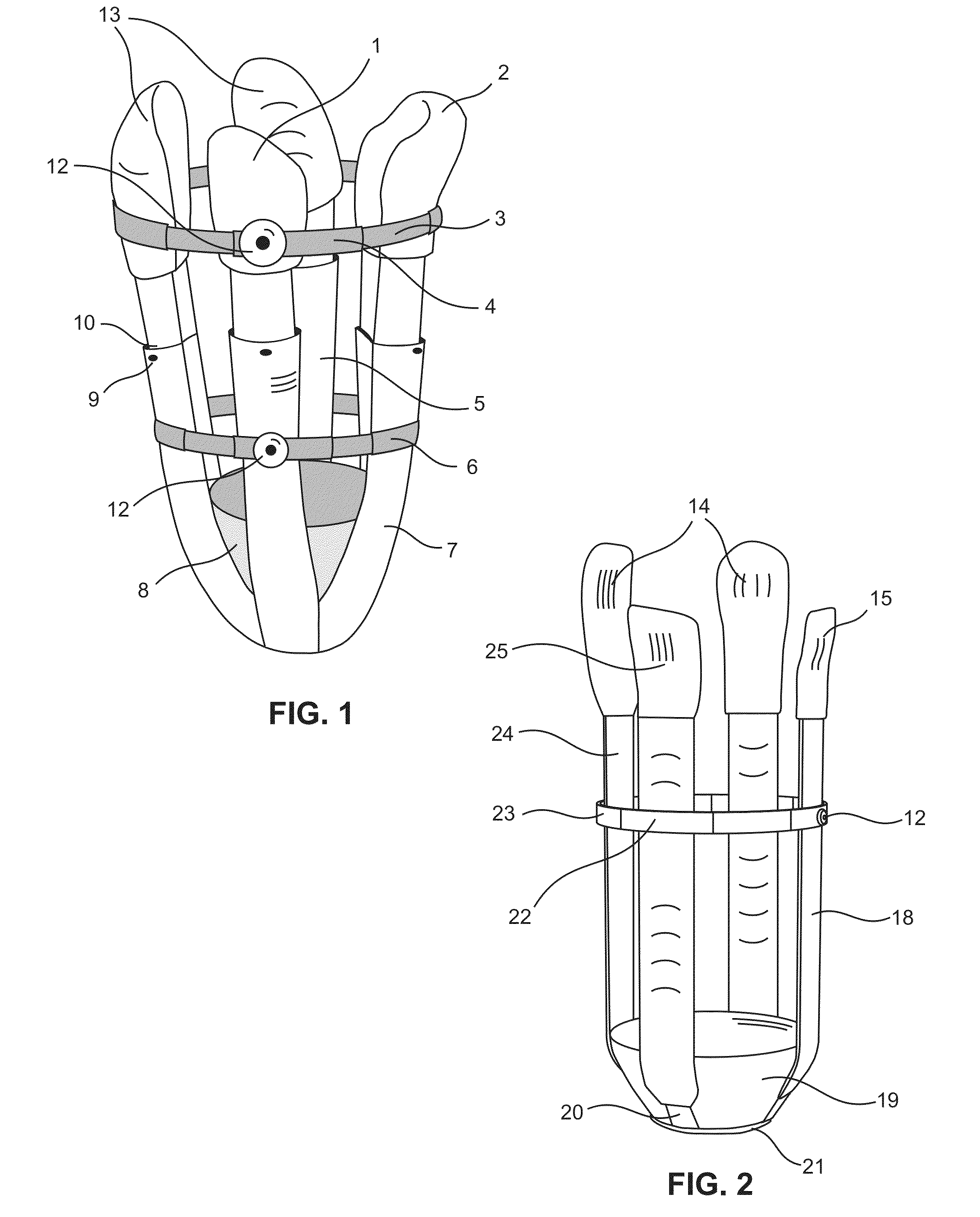
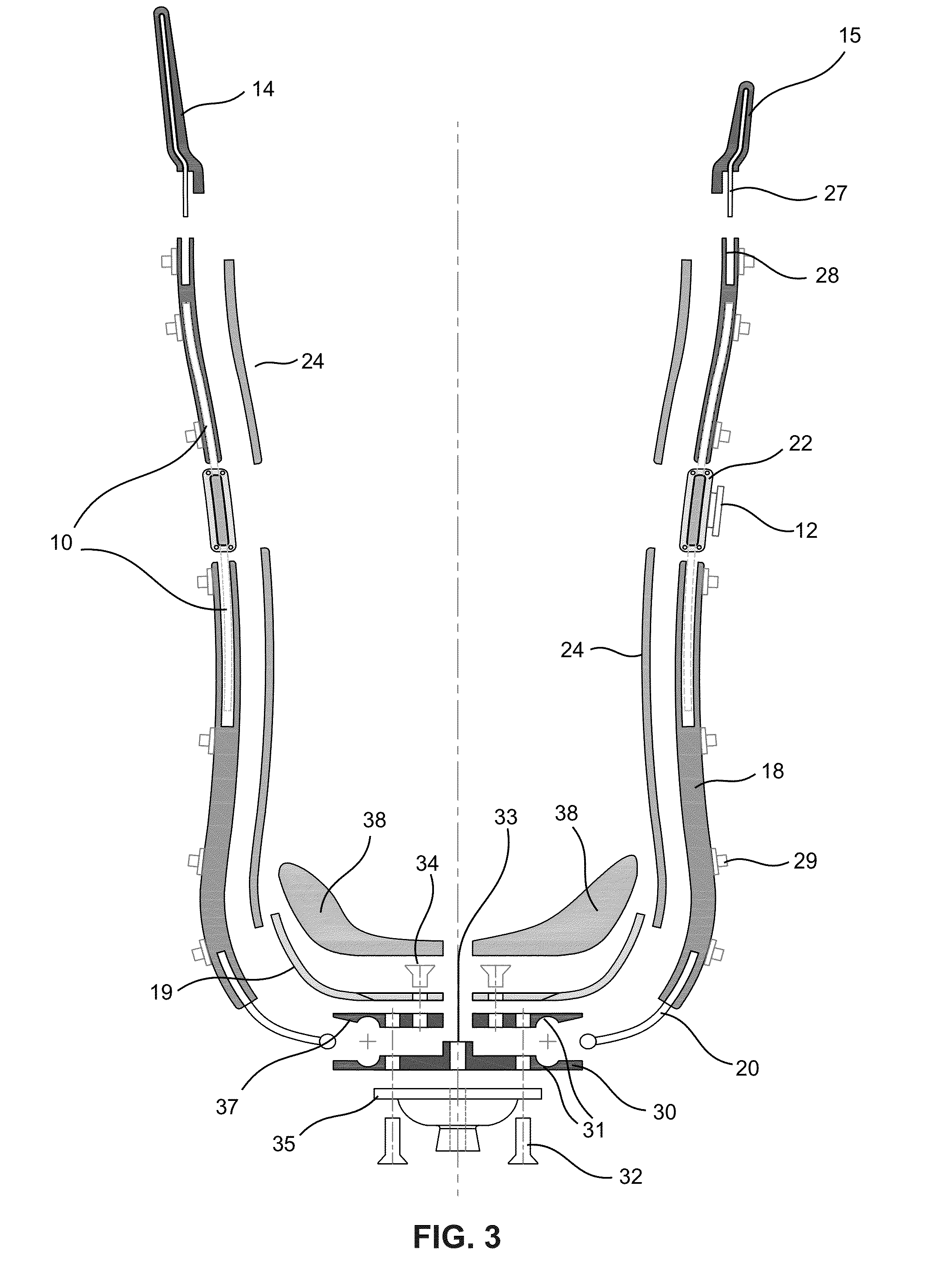
The invention is about a prosthetic socket system that can be adjusted to fit different types of residual limbs and to improve their biomechanical performance for various activities. The system includes modular components that can be adjusted in length, height, width, curvature, and flexibility. This allows for better fitting and more comfortable wearing of the prosthetic socket.

Problems solved by technology

The prosthetic socket is an important part of the prosthetic limb; if it does not operate properly, utility of the distal components can be severely compromised.
By this conventional fabrication approach, the degree of possible modification of the limb socket to optimize the fit of the residual limb socket is actually quite limited.
As may be understood from the foregoing brief summary of a conventional prosthetic fabrication process, there are aspects of the process that are less than satisfactory, largely associated with the centrality of physical molds within the process that transfer size and shape information from the residual limb that is reflected in the final prosthetic socket product.
The process is drawn out and time consuming, and inexact.
And the product, when formed and however satisfactory, is substantially fixed in form, and not readily modifiable.

Method used


Image

  • Modular prosthetic sockets and methods for making same
  • Modular prosthetic sockets and methods for making same
  • Modular prosthetic sockets and methods for making same

Examples


Embodiment Construction

Overview

[0106]The applicability of molds to the process of creating sockets that accommodate residual limbs and to provide a proximal base for effective prosthetic limbs and operable distal effectors is pervasive in the prior art, and has also been broadly helpful and therapeutically beneficial. As presented in the background, however, there are inherent and practical limitations to this approach. Such limitations relate to resources, such as time and cost, and to actualities of fit to a residual limb, wherein fit relates to a limb portion that is actually not well suited for bearing weight, providing a base of prosthetic limb operability. A residual limb comes with complications related to body heat and moisture that effect the interaction of the residual limb and the socket. And, the residual limb, itself, is dynamic in shape and internal structural details over time. These changes occur both in the short term, as during the course of a day, and in the long term, as the individual...


PUM

PropertyMeasurementUnit
Lengthaaaaaaaaaa
Pressureaaaaaaaaaa
Flexibilityaaaaaaaaaa

Abstract

The invention relates to a prosthetic socket for a residual limb of the lower extremity or upper extremity of an individual person. The residual limb has particular dimensions and anatomical contours; the prosthetic socket has dimensions and contours that fit the dimensions and contours of the residual limb. The prosthetic socket may also fit in a manner that is biomechanically particularly appropriate for the individual. The prosthetic socket is an assembly of components from groups of components that include (a) struts arranged longitudinally with respect to the residual limb, (b) proximal brim members arranged proximally to the struts and connected thereto; and (c) distal socket members disposed at the distal base of the prosthetic socket. The socket components within these groups may be modular in that they can vary with respect to dimensions and / or contours, and yet have common connecting features that permit assembly of the components together to form the prosthetic socket.

Description

RELATED APPLICATION[0001]This patent application claims the priority and benefit of commonly owned U.S. Provisional Patent Application Ser. No. 61 / 559,051 of Hurley, filed Nov. 12, 2011, entitled “Method for making a prosthetic socket, a modular system and resultant product of the process”, which provisional patent application is hereby incorporated by reference in its entirety into the present patent application.TECHNICAL FIELD[0002]The present invention relates to the field of prosthetics and orthotics. More particularly, the present invention relates to prosthetic sockets that are part of a prosthesis that is made to fit the residual limb of an amputee.BACKGROUND ART[0003]Current prosthetic limbs for the upper and lower extremity typically include a residual limb socket, an alignment system, and a functional component such as a knee, foot, or hand. For any prosthetic limb, a prosthetic socket is the portion of the prosthesis that is designed to fit and interface the residual limb...

Claims


Application Information

Patent Timeline
IPC IPC(8): A61F2/80A61F2/50
CPCA61F2/80Y10T29/49826A61F2/5046A61F2/5044A61F2/54A61F2/60A61F2/78A61F2/7812A61F2002/5026A61F2002/5027A61F2002/503A61F2002/5083A61F2002/546A61F2002/785A61F2230/0067A61F2230/0095Y10T29/4978
Inventor HURLEY, GARRETT RAYWILLIAMS, JESSE ROBERT
Owner LIM INNOVATIONS
Learn More