
Insulating Shipping System

a shipping system and insulation technology, applied in the field of insulation shipping systems, can solve the problems of large space to be shipped, low recycling rate of foam based technologies and/or products, and high cost of shipping

Inactive Publication Date: 2013-05-09
EKOPAK INC
View PDF5 Cites 101 Cited by
  • Summary
  • Abstract
  • Description
  • Claims
  • Application Information

AI Technical Summary

Benefits of technology

The patent describes a system that includes a container and an insert assembly. The insert assembly is made from a blank that has a center panel, two bottom panels with slots, and two top panels with tabs or flanges. The top panels have foldable lines of weakness and a foldable line of weakness between them. The system can be formed by inserting the top panels into the container and then coupling them together to form walled cavities. The system can also be made from recyclable materials and can be articulated to form a cavity within the container. The technical effects of this system include improved insulation, reduced weight, and improved durability.

Problems solved by technology

Most foam based technologies and / or products are not recyclable, at least not in the main recycling streams.
Foam based technologies and / or products usually are bulky and require a great deal of space to be shipped, which generally increases shipping costs.
Moreover, these containers generally are not reused.
Containers that are not recycled and not reused may end up in landfills, which may have negative effects on the environment.
Mineral rock wool is very dense and carries significant weight penalties when shipped, which may increase the cost to ship the container.
Further, mineral rock wool utilizes no post consumer recycled content and is not recyclable into the paper or poly waste streams.

Method used


Image

  • Insulating Shipping System
  • Insulating Shipping System
  • Insulating Shipping System

Examples


Embodiment Construction

[0034]While this invention is shown in the drawings and will be described in detail, the embodiments are described with the understanding that the present disclosure is to be considered as an exemplification of the principles of the invention and is not intended to limit the invention to the embodiments illustrated.

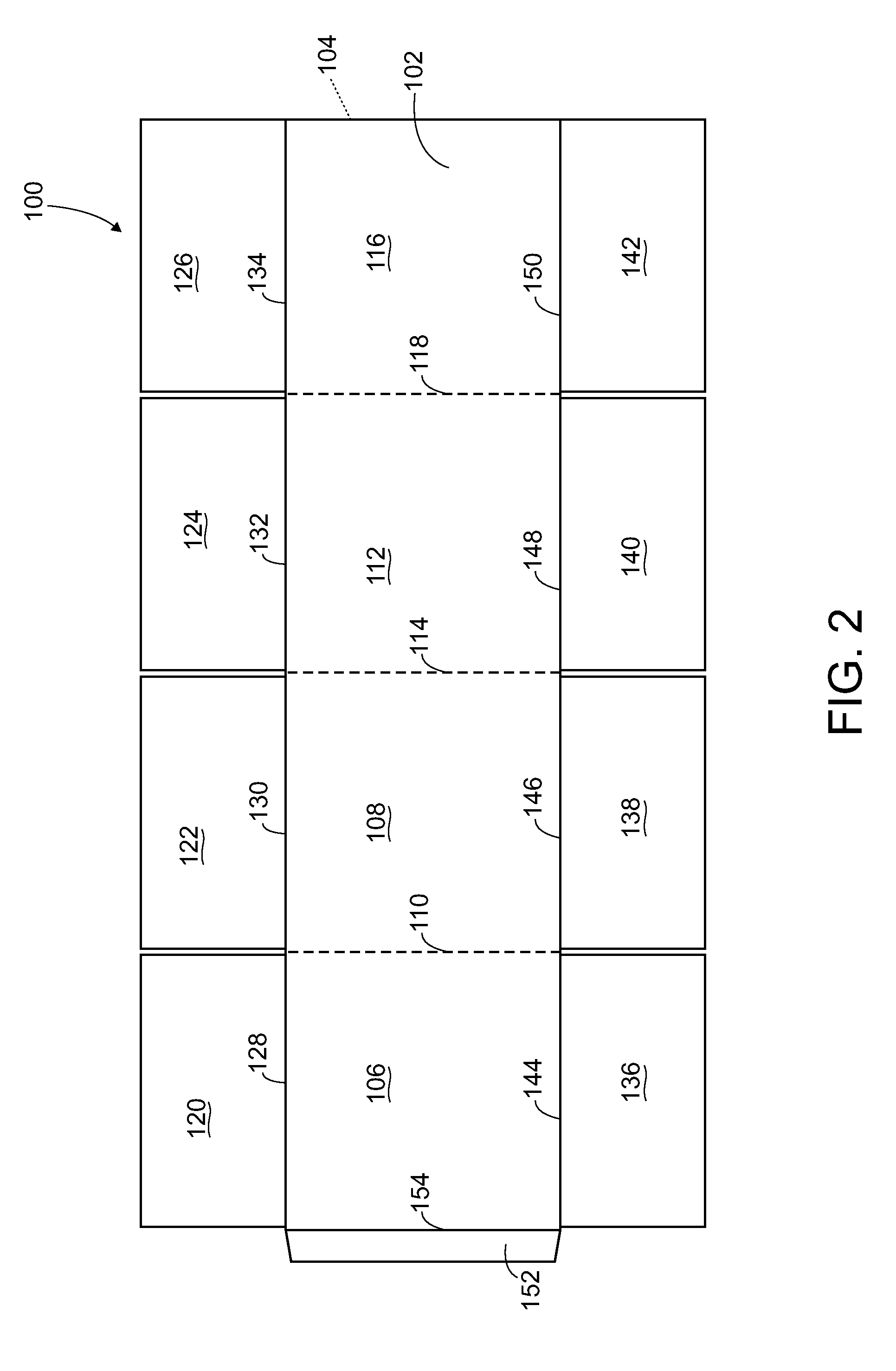
[0035]When referring to the plan illustrations of the blanks, the usual drawing conventions are applied. That is, unless otherwise noted, broken lines indicate lines of weakness, such as fold or score lines, which facilitate rotating or folding portions of a blank; and interior solid lines indicate through-cuts. Also, when score lines and / or fold lines are referred to herein, in alternative embodiments, a score line may be replaced with a fold line or another line of weakness, and / or a fold line may be replaced with a score line or another line of weakness.

[0036]Additionally, when flanges and / or tabs are referred to herein, in alternative embodiments, a flange may be repl...


PUM


Abstract

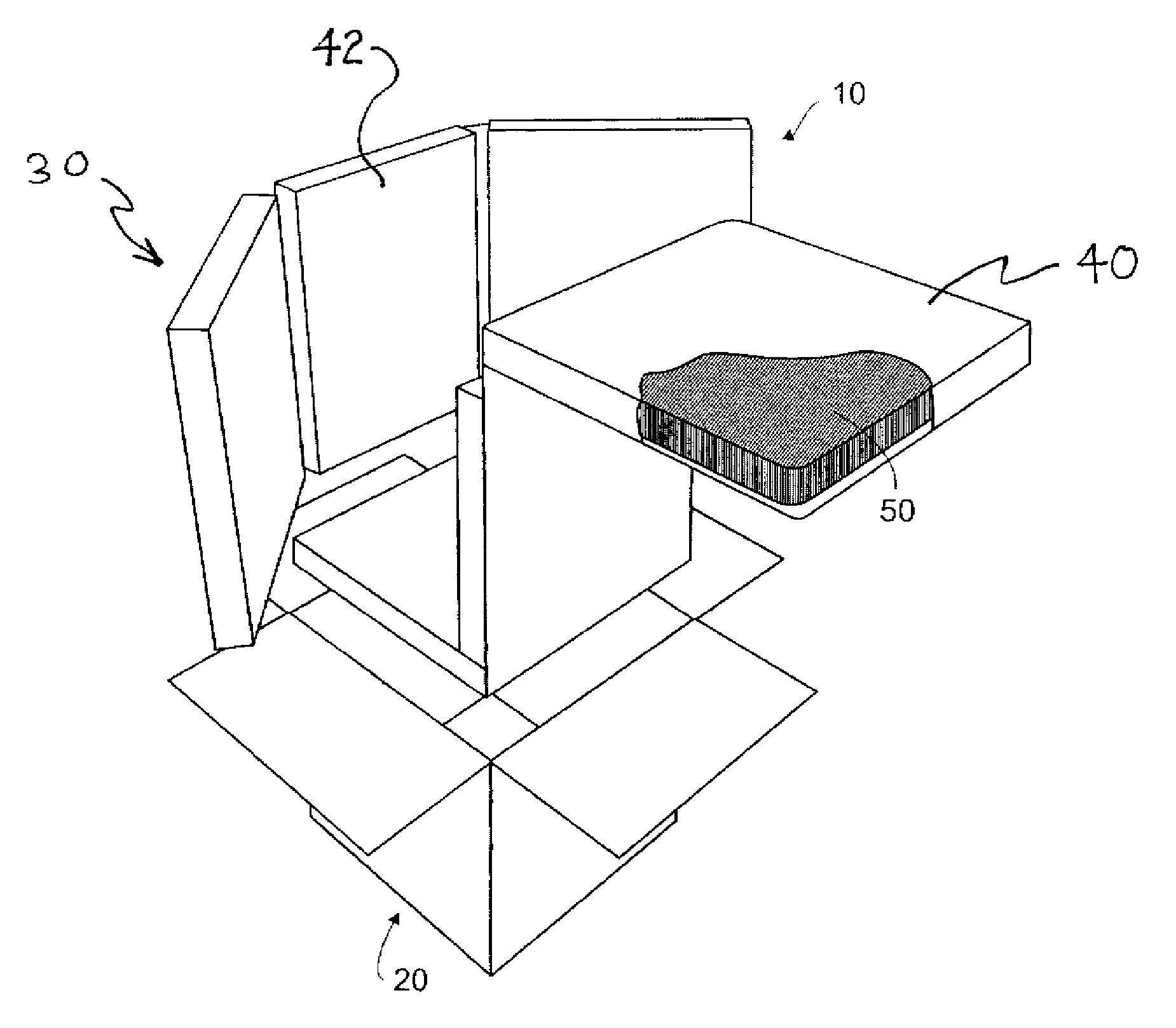
An insulating shipping system may include a container and an insert assembly which may include an insert configured to be inserted into the container. The insert may have a first blank that may include a center panel, two bottom panels emanating from opposite side edges, wherein each bottom panel has at least one slot, at least one top panel emanating from a top edge of each of the bottom panels, wherein each top panel has at least one tab or flange, and at least one foldable line of weakness disposed between each top panel and bottom panel, wherein the at least one slot is sized to receive the at least one tab or flange. The insert further may include a second blank have a center panel, wherein the center panel is configured to couple to the center panel of the first blank to form at least one walled cavity.

Description

BACKGROUND OF THE INVENTION[0001]1. Field of the Invention[0002]The present invention is directed generally to the field of insulated shipping systems.[0003]2. Description of the Related Art[0004]Various containers are designed to transport temperature sensitive items. Such containers traditionally are fabricated entirely from foam based technologies, such as expanded polystyrene (EPS) and / or urethane, wherein the foam based technologies generally provide insulation during transportation. Most foam based technologies and / or products are not recyclable, at least not in the main recycling streams. Foam based technologies and / or products usually are bulky and require a great deal of space to be shipped, which generally increases shipping costs.[0005]Other containers that are configured to transport temperature sensitive items may include a combination of materials, such as foam based technologies and / or paperboard. Most containers of this nature are not recycled, because the materials ...

Claims


Application Information

Patent Timeline
Patent Type & Authority Applications(United States)
IPC IPC(8): B65D81/38B31B1/02B31B17/00B31B1/26B31B11/02B65D5/42B31B1/50B31B50/02B31B50/50
CPCB65D81/3818B65D5/0227
Inventor HALL, CHRISTOPHER E.
Owner EKOPAK INC
Learn More