
Micro inertial measurement system

Active Publication Date: 2013-05-09
SZ DJI TECH CO LTD
View PDF15 Cites 53 Cited by
  • Summary
  • Abstract
  • Description
  • Claims
  • Application Information

AI Technical Summary

Benefits of technology

The present invention aims to solve the problems of traditional inertial measurement systems, such as being bulky and having limited damping frequency. The invention achieves increased rigidity and improved mechanical structure, reducing vibration and noise. The system's vibration characteristics are improved, and the volume and weight of the system are greatly reduced, expanding the load space of the carrier. The flexible measuring and controlling circuit boards cover the surfaces of the sensing support, making the system smoother and more efficient.

Problems solved by technology

Secondly, since the inertial measurement system has to bear vibration, impact and angular motion directly in a rigorous pneumatic environment, it is easy to bring about many destabilization effect and error effect, thereby becoming a weak link of the strapdown inertial navigation system.
Thirdly, there are some challenges such as micromation and industrialization for the strapdown inertial navigation system.
(1) the sensing support is composed of three circuit boards separated from each other, thus taking up too much space and resulting in significant differences among the rigidity on the three axial directions;
(2) since the damping units are installed outside of the inertial measurement system, they take up extra space; more importantly, when the inertial measurement unit is forced to vibrate, it is easy to have torsional vibration due to unbalanced rigidity and irrational mechanical structure;
(3) for the damper, its ideal sphere of action is limited to one-axis direction, that is, it can only attenuate the vibration from the vertical direction while having no effective suppression on the vibration from any other directions; as a result, linear vibration and angular vibration in different degrees of freedom can be coupled together and the damping band becomes narrow.

Method used


Image

  • Micro inertial measurement system
  • Micro inertial measurement system
  • Micro inertial measurement system

Examples


Embodiment Construction

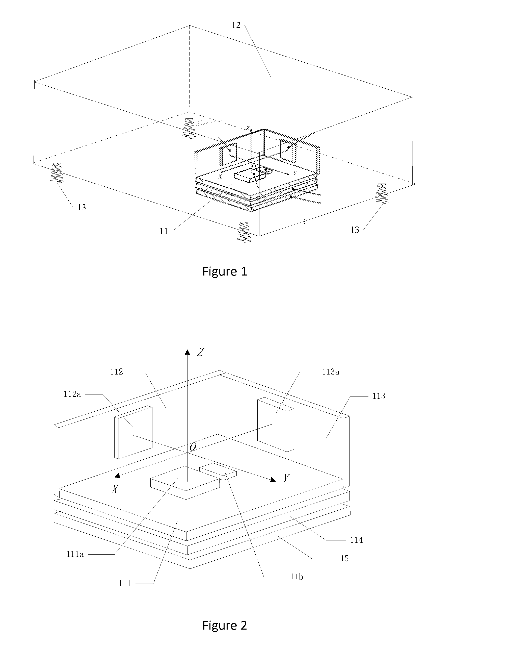
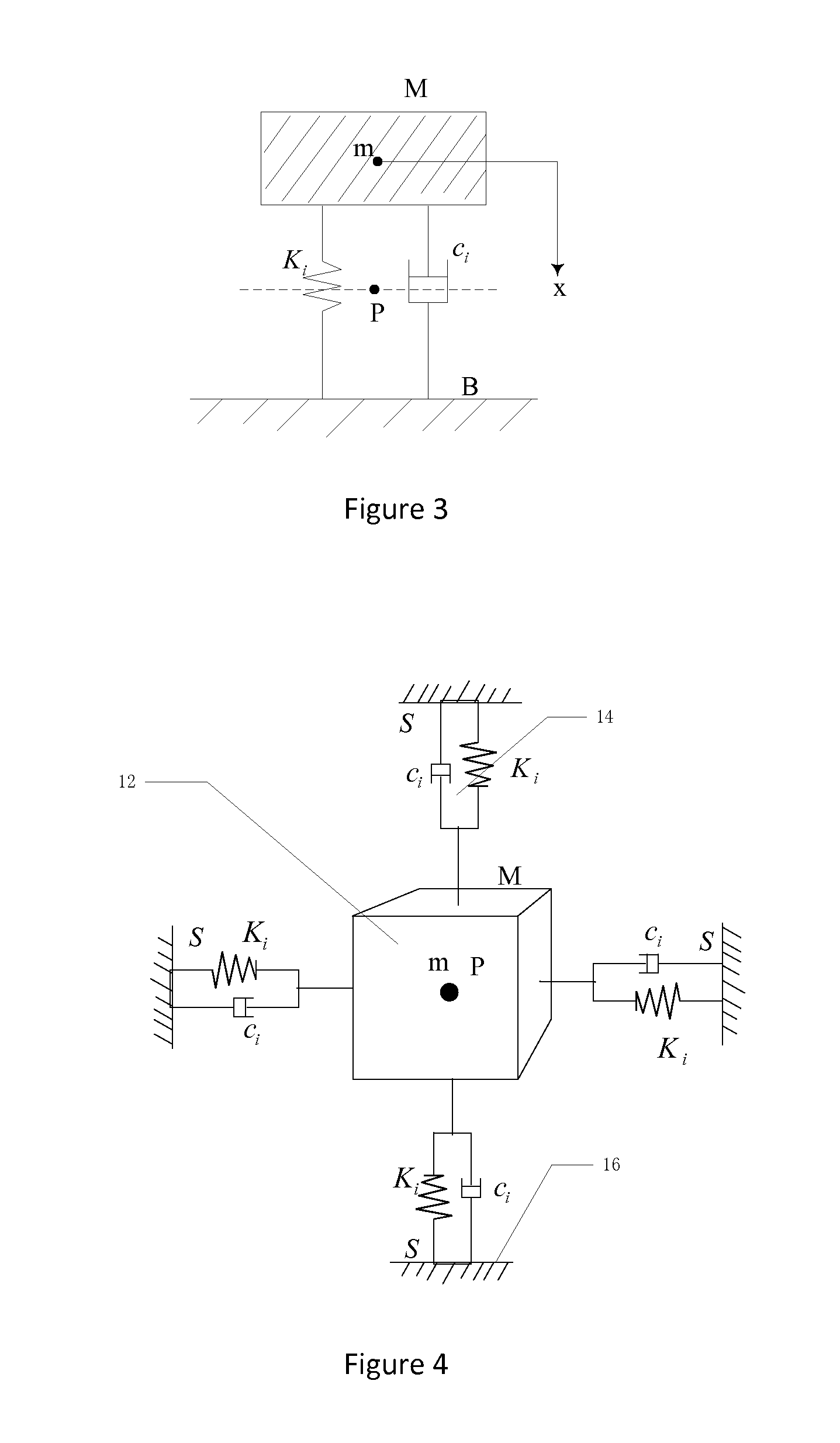
[0032]During operation, in the mechanical environment for a strapdown inertial navigation system, the violent random vibration may often present. The vibration may induce instability of the system and damage to electronic components, which will impact on the system stability greatly. In order to reduce such impact produced by the violent random vibration of a carrier, which may damage electronic components or make an inertial measurement unit unstable, except that the connection stiffness between respective sensor circuit boards is strengthened, the inertial measurement unit is elastically connected to the carrier using a damper as a damping medium, so as to realize a desired damping effect. Since the selection of a damping mode influences both damping performance and measurement precision of the inertial navigation system, it is always an important link in its structure design. In various aspects of the present invention, an improved design of sensing support and a rational damping...


PUM


Abstract

A micro inertial measurement system includes a housing, a sensing module, and a damper. The sensing module includes a rigid sensing support, a measuring and controlling circuit board mounted on the rigid sensing support and an inertial sensor set on the measuring and controlling circuit board. The inertial sensor includes a gyroscope and an accelerometer. The sensing module is mounted in the housing. The damper is mounted in the housing and set in the gap between the sensing module and the inside wall of the housing. By use of the above-mentioned structure, the noise immunity of the inertial measuring system can be greatly improved, and the volume and weight of the inertial measuring system can be greatly reduced.

Description

FIELD OF THE INVENTION[0001]The present invention relates to strapdown inertial navigation technology used in carriers such as unmanned aerial vehicle (UAV). More particularly, the present invention relates to a micro inertial measurement system used in strapdown inertial navigation,BACKGROUND OF THE INVENTION[0002]At present, strapdown inertial navigation is a type of booming and advanced navigation technology, Wherein, inertial elements including a gyroscope, an accelerometer and so on which are fixed to a carrier are directly uses for measuring an acceleration of the carrier relative to an inertial reference system. Then the information on the speed, attitude angle and position in a navigation coordinate system can be achieved by an integral operation based on the Newton law of inertia, so as to guide the carrier from a start point to a destination. Besides, in the strapdown inertial navigation technology, mathematical operations comprising coordination transformation and differe...

Claims


Application Information

Patent Timeline
IPC IPC(8): G01P15/14G01C19/02
CPCG01C21/16F16F15/04G01P15/14G01C21/166F16F15/022F16F15/085G01C19/5783G01P1/02G01P15/18
Inventor WANG, TAO
Owner SZ DJI TECH CO LTD
Learn More