Construction for mounting ultrasonic transducer and ultrasonic flow meter using same
- Summary
- Abstract
- Description
- Claims
- Application Information
AI Technical Summary
Benefits of technology
Problems solved by technology
Method used
Image

Examples
first exemplary embodiment
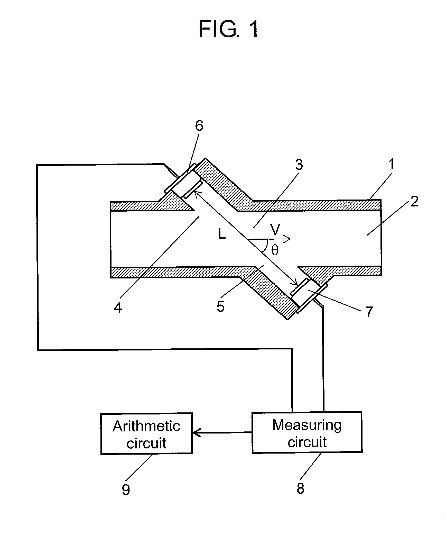
[0025]FIG. 1 illustrates configuration of an ultrasonic flowmeter employing an installation structure of an ultrasonic transducer in the first exemplary embodiment of the present invention.
[0026]In FIG. 1, fluid, such as LP gas and natural gas, passes through flow passage 2 configured in housing 1. Flow measuring part 3 is an area where a flow volume of fluid passing this flow passage 2 is measured. Ultrasonic transducer 6 is disposed in flow measuring part 3 at upstream side 4 of flow passage 2, and ultrasonic transducer 7 is disposed in flow measuring part 3 at downstream side 5 of flow passage 2.
[0027]Ultrasonic transducer 6 and ultrasonic transducer 7 are connected to measuring circuit 8 for measuring an ultrasonic propagation time between ultrasonic transducer 6 and ultrasonic transducer 7. Arithmetic circuit 9 is also provided for calculating a flow velocity and / or flow volume based on a signal from this measuring circuit 8.
[0028]A signal for emitting ultrasonic waves from ult...
second exemplary embodiment
[0045]FIG. 4 and FIG. 5 show a second exemplary embodiment of the present invention. FIG. 4 is a sectional view of attachment of an ultrasonic transducer, and FIG. 5 is a plan view of attachment of the ultrasonic transducer.
[0046]In FIG. 4, projection 32 is provided as a contact-restricting means at four points on a top part of step 31 of housing 30. These projections 32 prevent periphery 36 of terminal plate 35 from being in contact with side wall 30a of housing 30 when ultrasonic transducers 6 and 7 are mounted on O-ring 34 in attachment hole 33. Projection 32 has a shape that it makes linear-contact in the vertical direction with periphery 36 of terminal plate 35. Other structure and assembly method are the same as that shown in FIG. 2, and thus their description is omitted.
[0047]In this exemplary embodiment, periphery 36 of terminal plate 35 linearly contacts with projection 32 even if ultrasonic transducers 6 and 7 horizontally move when protrusions 29 of pressing means 24 pres...
third exemplary embodiment
[0050]FIG. 6 is a third exemplary embodiment of the present invention. FIG. 6 is a sectional view of attachment of an ultrasonic transducer. In FIG. 6, pressing means 37 includes protrusion 39 for being in contact with and urging terminal plate 38 of ultrasonic transducers 6 and 7 at three or more points, and support 41 for supporting ultrasonic transducers 6 and 7 toward the center of attachment hole 40 by being in contact with periphery 38a of terminal plate 8 at three or more points. Other structure and assembly method of other components including O-ring 42, housing 43, and screw 44 that is a locking means are the same as that in FIG. 2, and thus their description is omitted.
[0051]In this exemplary embodiment, periphery 38a of terminal plate 38 makes contact with support 41 when protrusion 39 of pressing means 37 presses ultrasonic transducers 6 and 7, and thus ultrasonic transducers 6 and 7 are prevented from moving horizontally. Accordingly, vibration of ultrasonic transducers...
PUM
 Abstract
Description
Claims
Application Information
 - R&D
- Intellectual Property
- Life Sciences
- Materials
- Tech Scout
- Unparalleled Data Quality
- Higher Quality Content
- 60% Fewer Hallucinations
Browse by: Latest US Patents, China's latest patents, Technical Efficacy Thesaurus, Application Domain, Technology Topic, Popular Technical Reports.
© 2025 PatSnap. All rights reserved.Legal|Privacy policy|Modern Slavery Act Transparency Statement|Sitemap|About US| Contact US: help@patsnap.com