
Injection needle assembly and drug injection device

a technology of injection needles and injection needles, which is applied in the direction of intravenous devices, etc., can solve the problems of difficult administration of influenza vaccines according to mantoux and difficult drug administration procedures based on mantoux methods

Active Publication Date: 2013-04-18
TERUMO KK
View PDF2 Cites 24 Cited by
  • Summary
  • Abstract
  • Description
  • Claims
  • Application Information

AI Technical Summary

Benefits of technology

The injection needle assembly and drug injection device of this patent invention can quickly and reliably puncture the needle in a living body, allowing for easy and accurate drug injection. This is achieved through the use of a puncture speed securing member that ensures the needle punctures with speed and force. In addition, the device allows for easy adjustment for different injection targets, making it simple and efficient to use.

Problems solved by technology

The administration procedure of a drug based on the Mantoux method is difficult, with its success rate being entrusted to the skill of a doctor who makes an injection.
Especially, children are apt to act up upon administration and thus, it has been difficult to administer an influenza vaccine according to the Mantoux method.

Method used


Image

  • Injection needle assembly and drug injection device
  • Injection needle assembly and drug injection device
  • Injection needle assembly and drug injection device

Examples


first embodiment

1. First Embodiment

1-1. Configuration Examples of Injection Needle Assembly and Drug Injection Device

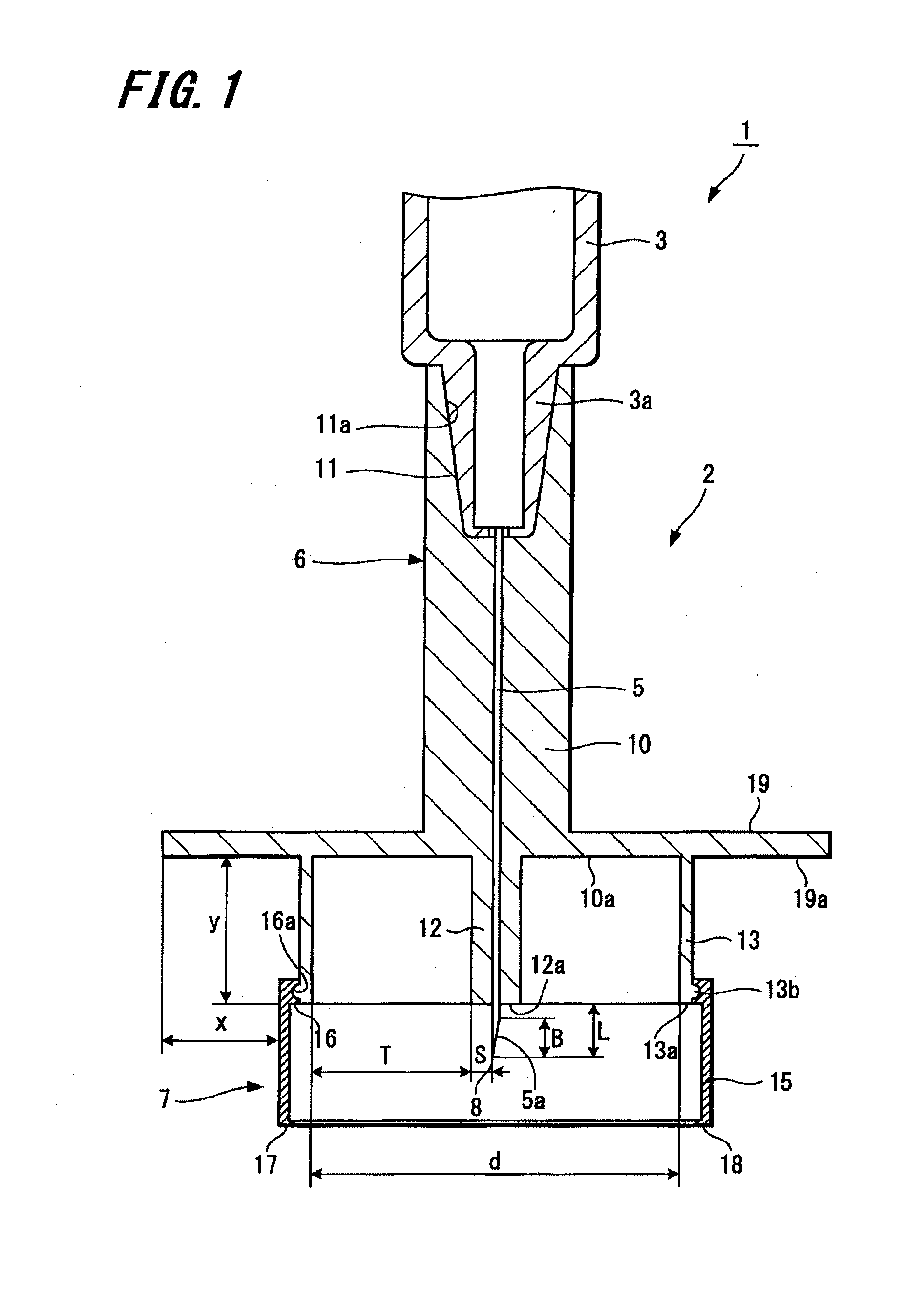
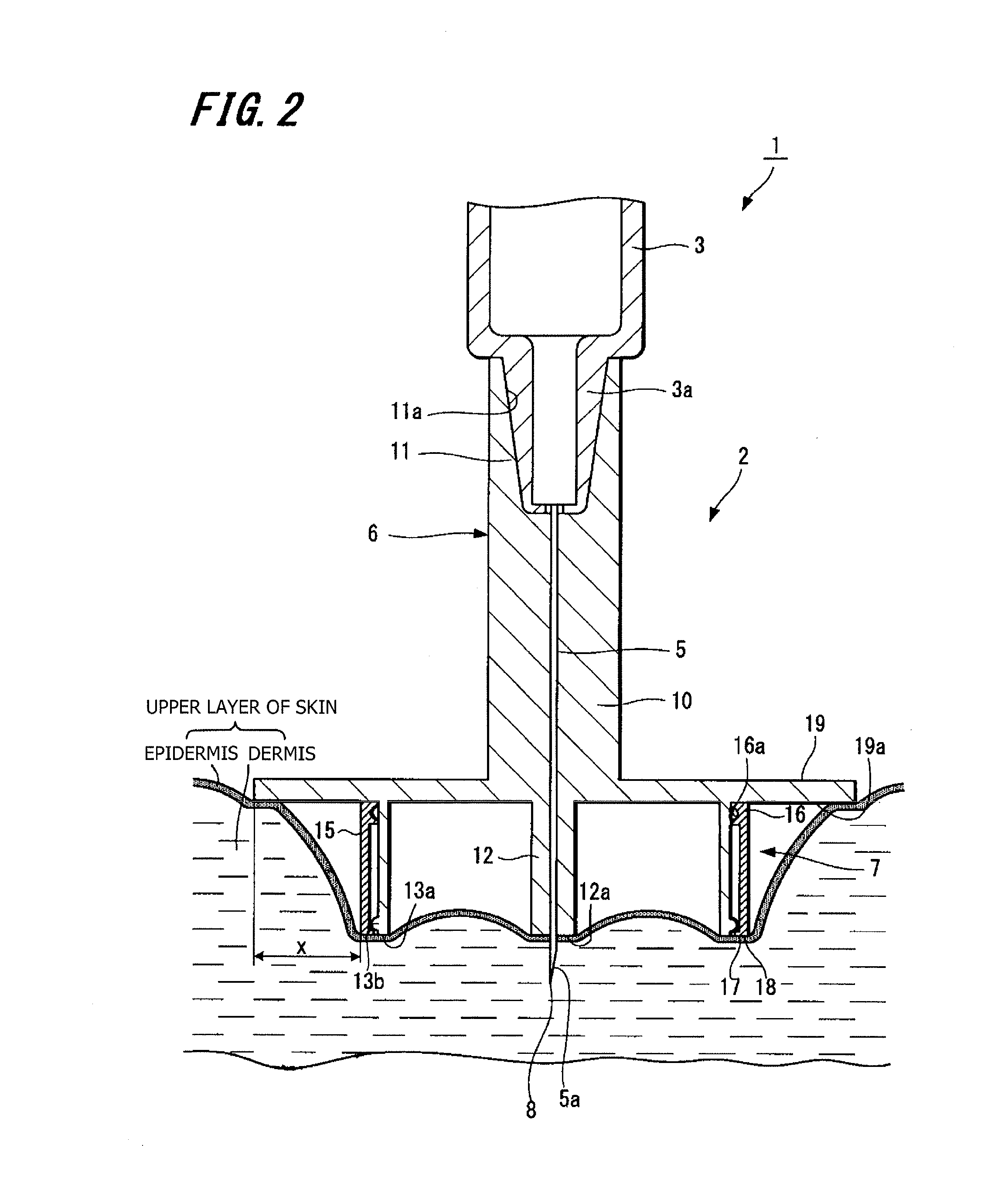
[0028]Initially, an injection needle assembly and drug injection device according to a first embodiment (hereinafter referred to as “this embodiment”) of the invention are described with reference to FIGS. 1 to 2.

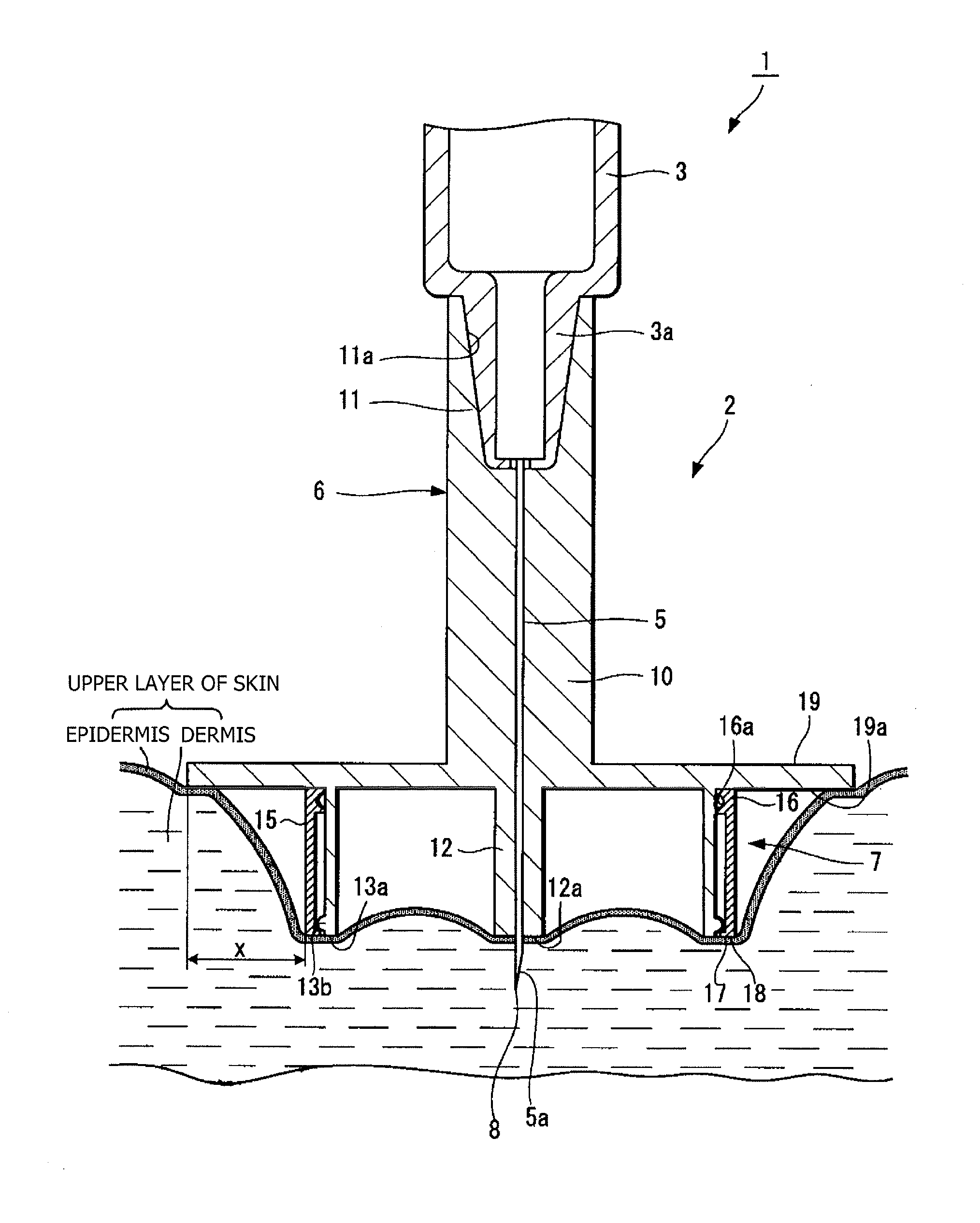
[0029]FIG. 1 is a sectional view showing a drug injection device of this embodiment, and FIG. 2 is a section view showing a state where the device is punctured.

[0030]As shown in FIG. 1, a drug injection device 1 is composed of an injection needle assembly 2, and a syringe 3 to which the injection needle assembly 2 is detachably connected. The syringe 3 may be either one wherein a drug is filled at the time when the drug injection device is used or a pre-filled syringe having a drug filled beforehand. As a drug to be filled in the syringe 3, mention is made of vaccines. High molecular substances such as cytokine, and hormones may also be used.

[0031]The injection needle assemb...

second embodiment

2. Second Embodiment

[0085]Next, a second embodiment of a drug injection device of the invention is described with reference to FIGS. 3 and 4.

[0086]FIGS. 3 and 4 are, respectively, a sectional view showing a drug injection device according to the second embodiment.

[0087]A drug injection device 21 related to the second embodiment differs from the drug injection device 1 of the first embodiment in that the puncture speed securing member is disposed at the adjustment section. The puncture speed securing member and adjustment section are described herein and like portions common with the drug injection device 1 are indicated by like reference numerals for avoiding redundancy.

[0088]As shown in FIG. 3, an adjustment section 22 is disposed at a central portion of one end face 10a of a hub body 10 and is configured as a substantially cylindrical protrusion portion projecting in an axial direction of the hub body 10. At an end portion of the adjustment section 22 at a side opposite to the hub...

third embodiment

3. Third Embodiment

[0098]Next, a third embodiment of a drug injection device of the invention is described with reference to FIGS. 5 and 6.

[0099]FIGS. 5 and 6 are, respectively, a sectional view showing a drug injection device according to the third embodiment.

[0100]A drug injection device 31 according to the third embodiment includes a modified configuration of the puncture speed securing member and the adjustment section of the drug injection device 21 of the second embodiment. Hence, a puncture speed securing member and adjustment section are illustrated herein. Like portions common with the drug injection device 1 are indicated by like reference numerals for avoiding redundancy.

[0101]As shown in FIG. 5, an adjustment section 32 has a needle projection surface 32a, a portion 32b to be engaged and a portion 32c to be fitted. The needle projection surface 32a is an end face at an opposite side of a hub body 10 in the adjustment section 32, from which the needle tip 8 of the needle ...


PUM


Abstract

Objects are to ensure a required depressing force and puncture speed when a needle tube is punctured in the skin, and to be able to reliably situate a needle tip of a needle tube in the upper layer of skin. A needle injection assembly 2 includes a needle tube 5 having a needle tip 8 that can be punctured in a living body, a hub 6 that holds the needle tube 5, an adjustment section 12, a stabilizing section 13, and a puncture speed securing member 7. The adjustment section 12 is provided around the periphery of the needle tube 5 and has a needle projection surface 12a, from which the needle tip 8 of the needle tube 5 projects. The stabilizing section 13 extends from the hub 6, is disposed to surround the needle tube 5 and has an end face 13a that comes in contact with the skin when the needle tube 5 is punctured in the living body. The puncture speed securing member is provided at the adjustment section 12 or stabilizing section 13 such that the puncture speed securing member moves along the axial direction of the needle tube 5. The puncture speed securing member 7 is brought into contact with the skin ahead of the needle tip 8 of the needle tube 5 when the needle tube 5 is punctured in the living body and ensures the speed and depressing force as desired when the needle tube 5 is punctured in the living body.

Description

TECHNICAL FIELD[0001]This invention relates to an injection needle assembly and drug injection device, which are used to cause a needle tip to be punctured from a skin surface so as to inject a drug into the upper layer of skin.BACKGROUND ART[0002]In recent years, avian influenza infection in humans has been reported with concern that much damage is caused by infectious human-to-human pandemic outbreak. Therefore, there have been being built, in the world, stockpiles of a pandemic vaccine that would have the high possibility of being effective against the avian influenza. In order to administer the pandemic vaccine to many people, studies have been made on the increasing amount of production of the vaccine.[0003]The skin is made up of three layers including the epidermis, the dermis and the subcutis. The epidermis is a layer of about 50 to 200 μm from the skin surface, and the dermis is a layer of about 1.5 to 3.5 mm contiguous to the epidermis. Generally, an influenza vaccine is su...

Claims


Application Information

Patent Timeline
IPC IPC(8): A61M5/46
CPCA61M5/3287A61M5/46A61M5/42
Inventor KAWAMOTO, HIDEOOYAUCHI, TETSUYA
Owner TERUMO KK
Learn More