Imaging device, imaging method and storage medium
- Summary
- Abstract
- Description
- Claims
- Application Information
AI Technical Summary
Benefits of technology
Problems solved by technology
Method used
Image

Examples
first embodiment
A. First Embodiment
A-1. Structure of the First Embodiment
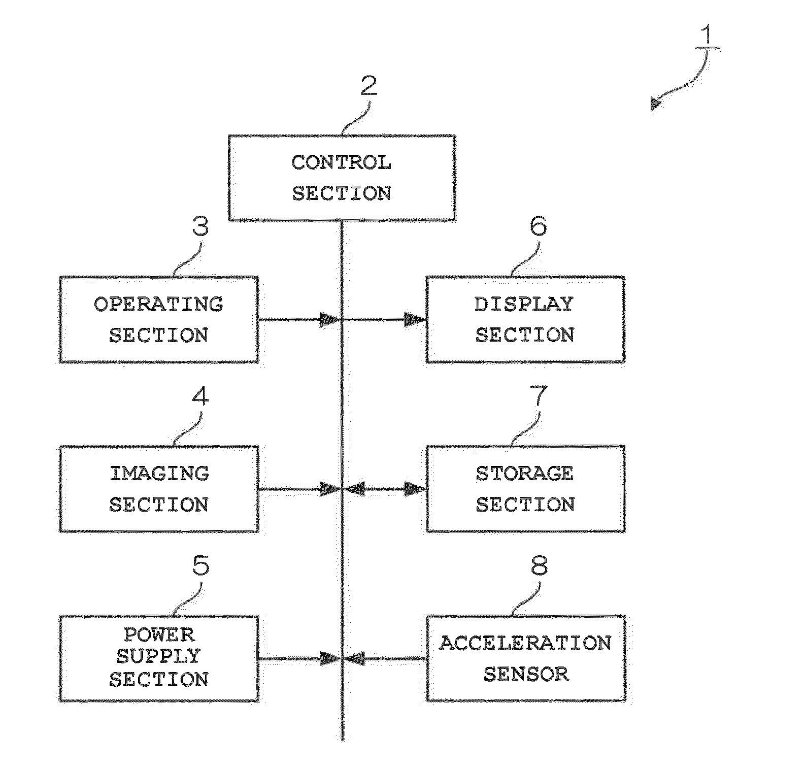
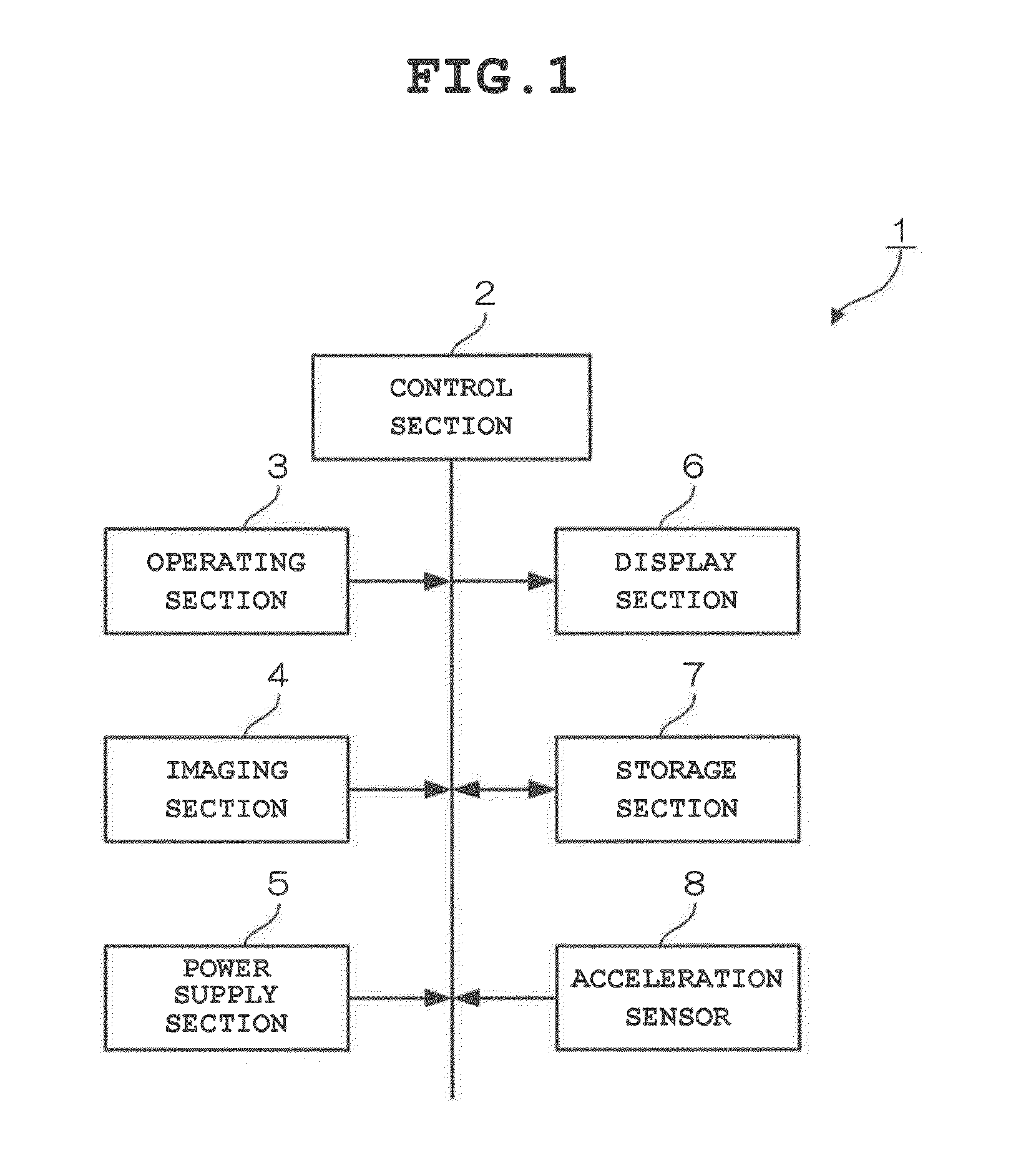
[0026]FIG. 1 is a block diagram showing the structure of an imaging device 1 according to a first embodiment of the present invention. The imaging device 1 in FIG. 1 includes a control section 2, an operating section 3, an imaging section 4, a power supply section 5, a display section 6, a storage section 7 and an acceleration sensor 8. The control section 2 is a single-chip microcomputer that controls each section of the imaging device 1. In particular, according to the first embodiment, the control section 2 acquires a movement direction, a movement amount and orientation (vertical orientation or horizontal orientation) of the imaging device 1 based on output from the acceleration sensor 8. Also, when the movement direction of the imaging device 1 in the beginning of imaging is substantially linear and a substantially horizontal or vertical direction, the control section 2 calculates a reference movement amount in the direct...
second embodiment
B. Second Embodiment
[0063]Next, a second embodiment of the present invention will be described.
B-1. Structure of the Second Embodiment
[0064]In the above-described first embodiment, the guides 12a and 12b, or 12c are displayed having an aspect ratio that forms a horizontally long area, on the assumption that the initial movement direction in the beginning of imaging is substantially linear and a substantially horizontal direction. However, in the second embodiment, when the movement direction of the initial movement in the beginning of imaging is substantially linear and a substantially horizontal direction, the reference movement amount is calculated based on an aspect ratio that forms a horizontally long area, and when it is substantially linear and a substantially vertical direction, the reference movement amount is calculated based on an aspect ratio that forms a vertically long area. As a result, an aspect ratio that forms a horizontally long area or an aspect ratio that forms a...
third embodiment
C. Third Embodiment
[0083]Next, a third embodiment of the present invention will be described.
C-1. Structure of the Third Embodiment
[0084]In the third embodiment, a position to be the center of a composite image is specified at the start of the imaging, and the reference movement amount is calculated based on a movement amount from the specified position. As a result of this configuration, a subject to be placed in the center of a composite image can be specified at the beginning, and whereby the composition of the composite image can be easily decided. Note that the structure of the imaging device 1 in the third embodiment is the same as that in FIG. 1, and therefore explanation thereof is omitted.
C-2. Operations of the Third Embodiment
[0085]Next, operations of the third embodiment will be described.
[0086]FIG. 11 and FIG. 12 are flowcharts for describing operations of the imaging device 1 according to the third embodiment, and FIG. 13A to FIG. 13G are schematic diagrams showing exam...
PUM
 Abstract
Description
Claims
Application Information
 - R&D
- Intellectual Property
- Life Sciences
- Materials
- Tech Scout
- Unparalleled Data Quality
- Higher Quality Content
- 60% Fewer Hallucinations
Browse by: Latest US Patents, China's latest patents, Technical Efficacy Thesaurus, Application Domain, Technology Topic, Popular Technical Reports.
© 2025 PatSnap. All rights reserved.Legal|Privacy policy|Modern Slavery Act Transparency Statement|Sitemap|About US| Contact US: help@patsnap.com