
Aeroelastic tuned mass damper

a damper and tuned technology, applied in the direction of shock absorbers, machines/engines, transportation and packaging, etc., can solve the problems of reducing the capability of aircraft, extending the design lead time, and affecting the performance of aircra

Active Publication Date: 2013-04-18
THE BOEING CO
View PDF45 Cites 8 Cited by
  • Summary
  • Abstract
  • Description
  • Claims
  • Application Information

AI Technical Summary

Benefits of technology

The patent text discusses a method for reducing aeroelastic modes in an aircraft. These modes can cause instability in the aircraft during flight. The method involves attaching a tuned mass damper to an attachment point in the aircraft. The tuned mass damper is designed to reduce the motion at a specific location in the aircraft. This can help to stabilize the aircraft and make it more reliable during flight. The tuned mass damper is made up of a primary mass and tuning masses that are concentrically mounted on a shaft with springs and a viscous damper. The system can be installed in the nacelle of the aircraft and can be designed to move back and forth in the inboard and outboard directions. The method and design of the tuned mass damper can be applied to different types of aircraft and can help to make them safer and more reliable during flight.

Problems solved by technology

However, in certain cases aeroelastic designs may be subject to resonant oscillations created under certain aerodynamic conditions and at various speeds.
Payload or fuel restrictions will typically reduce capability of the aircraft while active modal suppression requires extensive design and experimentation resulting in extended design lead time and may also affect performance.
Use of ballast results in a significant increase in weight which may affect performance and may drive structural changes and inherent structural changes for stiffness also typically add weight.
Vortex generators, while often effective for localized oscillation suppression are not typically effective for full airplane LCO

Method used


Image

  • Aeroelastic tuned mass damper
  • Aeroelastic tuned mass damper
  • Aeroelastic tuned mass damper

Examples


Embodiment Construction

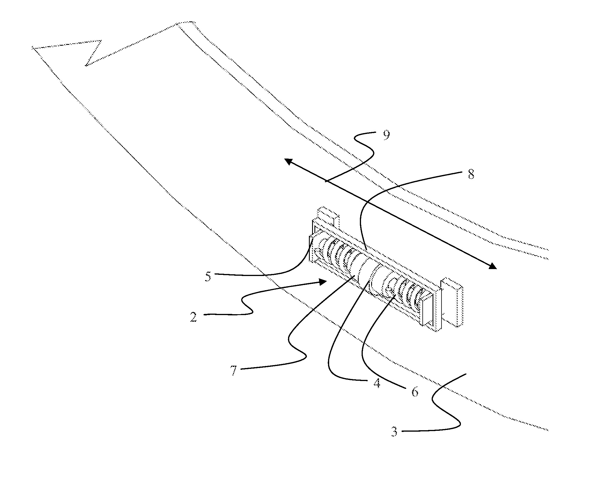
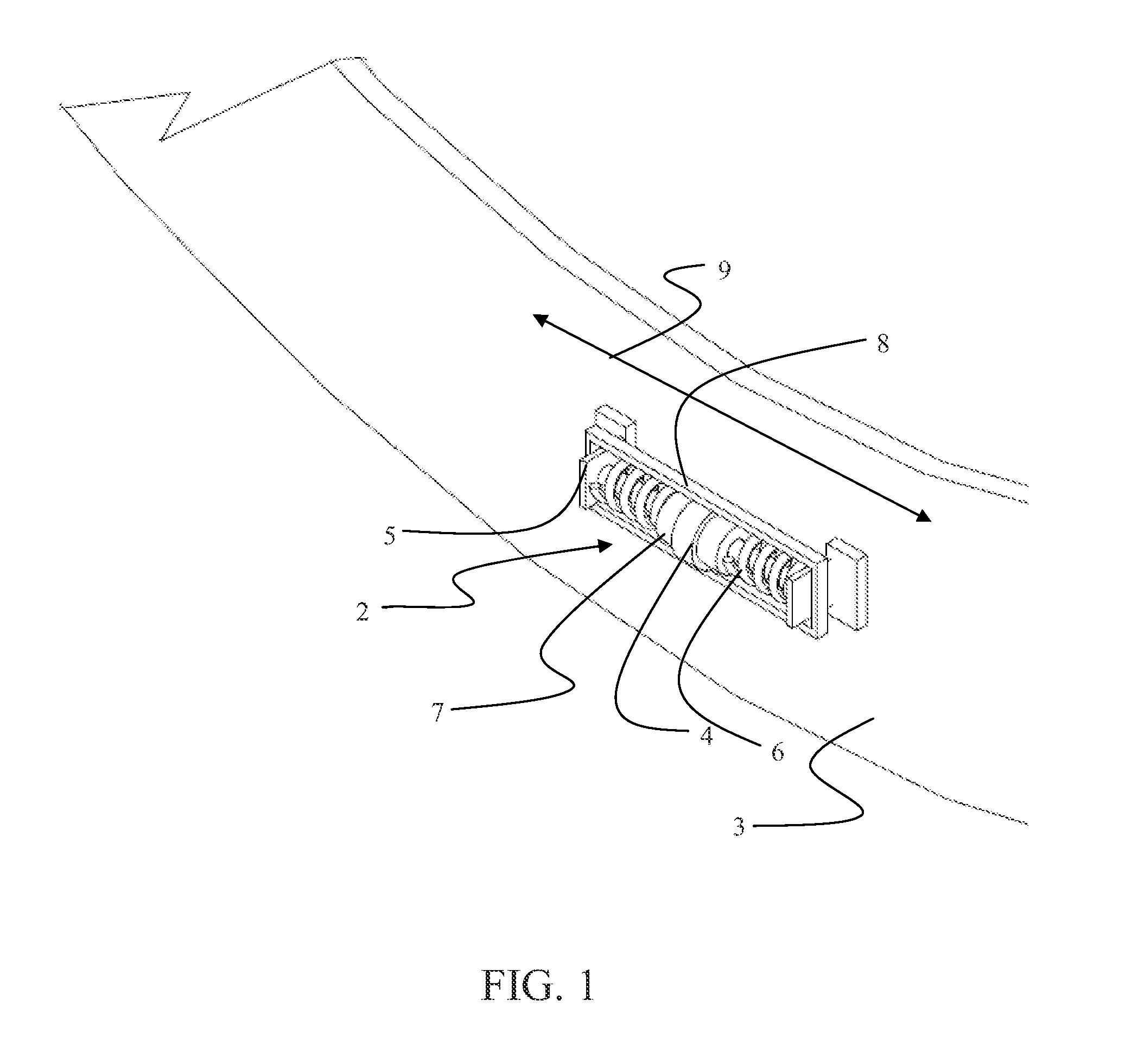
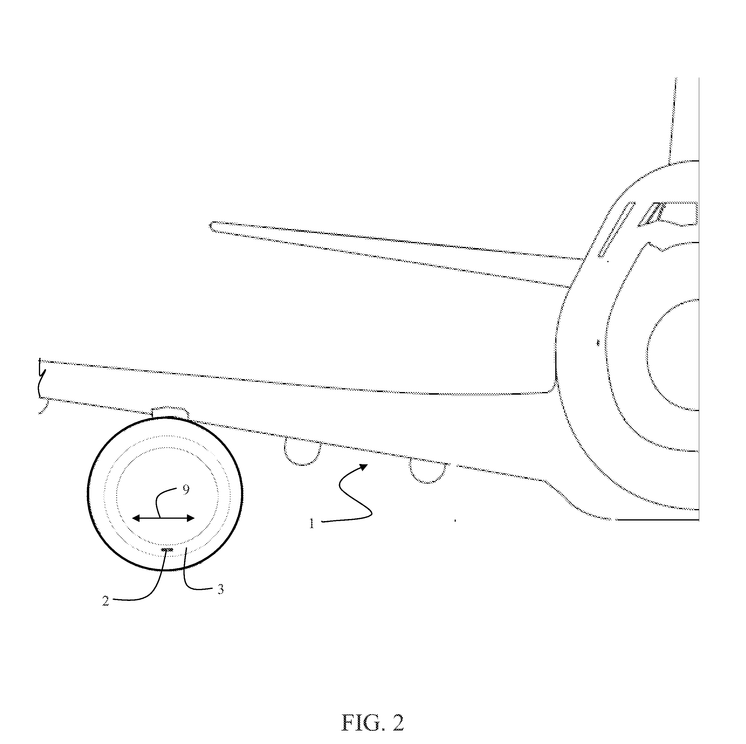
[0031]Embodiments disclosed herein provide a tuned mass damper (TMD) to dampen aeroelastic modes involving the complete primary structure including whole airframe limit cycle oscillation (LCO) vibration involving the powerplant, wing and fuselage. In an example embodiment, the tuned mass damper is attached to the nacelle in the region of the lower fan case. In alternative embodiments, the damper may be attached to one or more of the airplane nacelles, (or other locations on the airframe). For the embodiment described in detail subsequently, the TMD is located in the lower forward nacelle inlet cowl in a horizontal position with inboard and outboard motion of the mass to maximize effectiveness for an airplane LCO mode which has significant displacement at this location and direction. The TMD frequency is equal to the modal frequency for which suppression is desired. The mass is mounted to move with minimal Coulomb friction and is provided with an optimized amount of viscous damping (...


PUM


Abstract

A method for damping aeroelastic modes, including limit cycle oscillations (LCO), is implemented by determining a mass for a tuned mass damper (TMD) based on an modal frequency for a mode having a potentially positive growth rate and attaching a TMD to at least one attachment point with significant motion such that a damping axis of the tuned mass damper is substantially oriented in a direction aligned with the local modal deflection.

Description

BACKGROUND INFORMATION[0001]1. Field[0002]Embodiments of the disclosure relate generally to the field of vibration reduction systems for aircraft and more particularly to a plurality of tuned mass dampers having viscous damping and mounted in multiple locations on the airframe with directional orientation determined to maximize damping of primary modes of aeroelastic limit cycle oscillation.[0003]2. Background[0004]Large modern commercial jet aircraft are designed with consideration of the aeroelastic stability of the aircraft. However, in certain cases aeroelastic designs may be subject to resonant oscillations created under certain aerodynamic conditions and at various speeds. Such oscillations can be localized in certain portions of the airframe or may be whole airframe aeroelastic modes including limit cycle oscillations (LCO) involving the nacelles, wing and fuselage.[0005]To minimize LCO, prior art aeroelastic solutions include payload and / or fuel restrictions, active modal su...

Claims


Application Information

Patent Timeline
Patent Type & Authority Applications(United States)
IPC IPC(8): F16F7/104F16F7/112
CPCF16F7/116Y02T50/671F05D2260/96F02C7/00B64D29/00Y02T50/60
Inventor HAGELIN, JACK S.RUEGAMER, SASCHA K.THORNTON, TIM D.O'MEARA, SEAN C.ELLIS, JEFFREY R.GYLLAND, JR., E. FRED
Owner THE BOEING CO
Learn More