
Ball acupressure device

a technology of acupressure device and ball, which is applied in the field of ball acupressure device, can solve the problems of reducing the portability, affecting the function of the acupressure device, and the difficulty of smoothly rotating the acupressure part only with the rotational force of the upper ring, so as to improve the functional efficiency, improve the use effect, and reduce the frictional resistance of the first rotating ring and the second rotating ring.

Inactive Publication Date: 2013-04-11
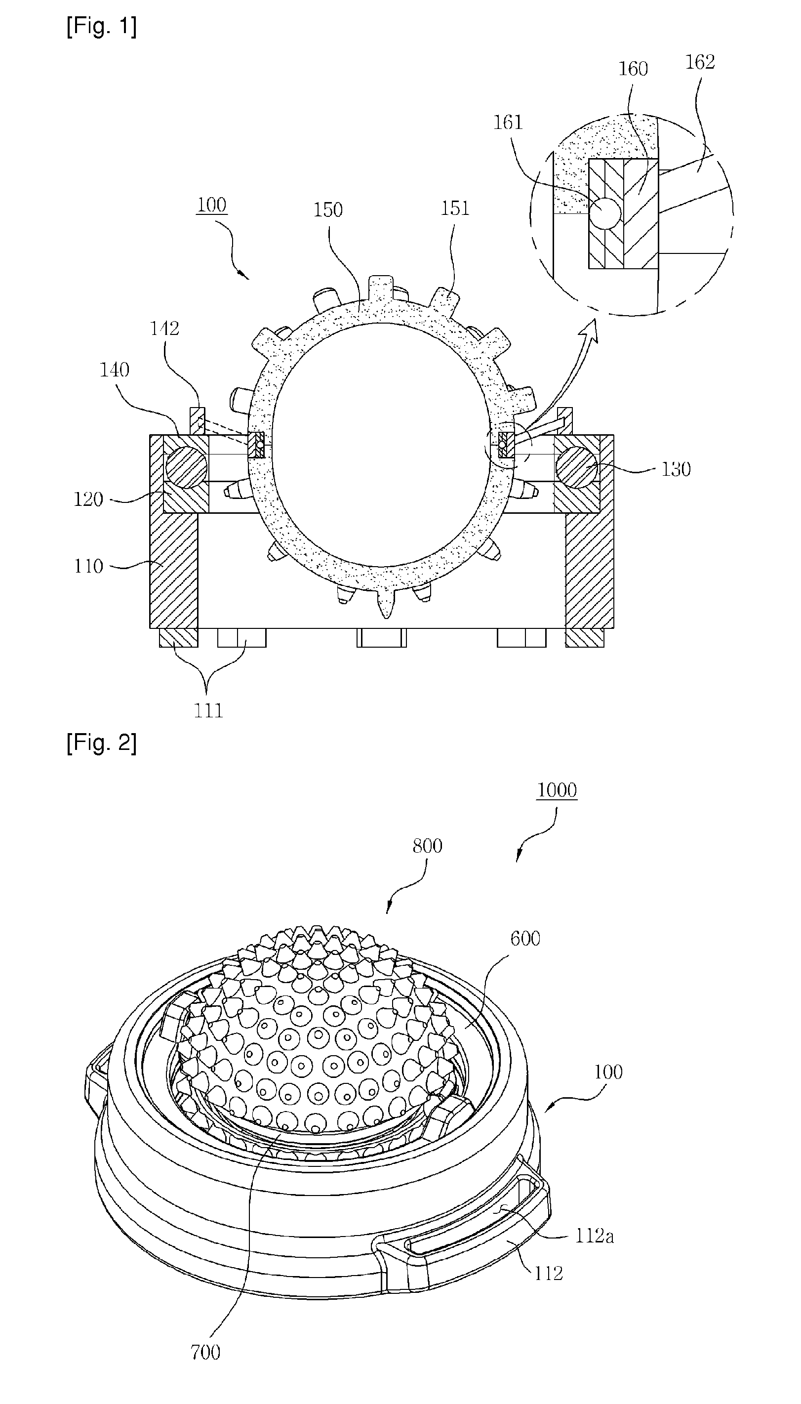
KWANG ZIN
View PDF5 Cites 12 Cited by
  • Summary
  • Abstract
  • Description
  • Claims
  • Application Information

AI Technical Summary

Benefits of technology

The present invention provides a device with a separation preventing protrusion in the housing body, which prevents components from escape or damage, increasing the usability and functional efficiency of the device. Additionally, the device includes ball bearings and interiors for smoother and easier rotation of the components. The hinge rod formed on the clamp allows for continuous and rapid rotation in all directions of 360 degrees. These technical features enhance the overall performance of the device and make it more user-friendly.

Problems solved by technology

However, since the acupressure device according to the prior art has a structure in which the lower ring, the bearing, and the upper ring are sequentially stacked in the open hollow of the housing in a simple inserting manner, when the open hollow of the housing is tilted vertically or turned upside down, all internal components are separated from the housing, thus decreasing the portability, or when the housing drops from a predetermined height, the respective components that constitute the acupressure device are easily damaged by the impact.
Moreover, since the housing is in contact with a locking protrusion of the housing and thus cannot rotate, it is difficult to smoothly rotate the acupressure part only with the rotational force of the upper ring.

Method used


Image

  • Ball acupressure device
  • Ball acupressure device
  • Ball acupressure device

Examples


Embodiment Construction

[0027]Hereinafter, preferred embodiments of the present invention will be described in detail with reference to FIGS. 2 to 4.

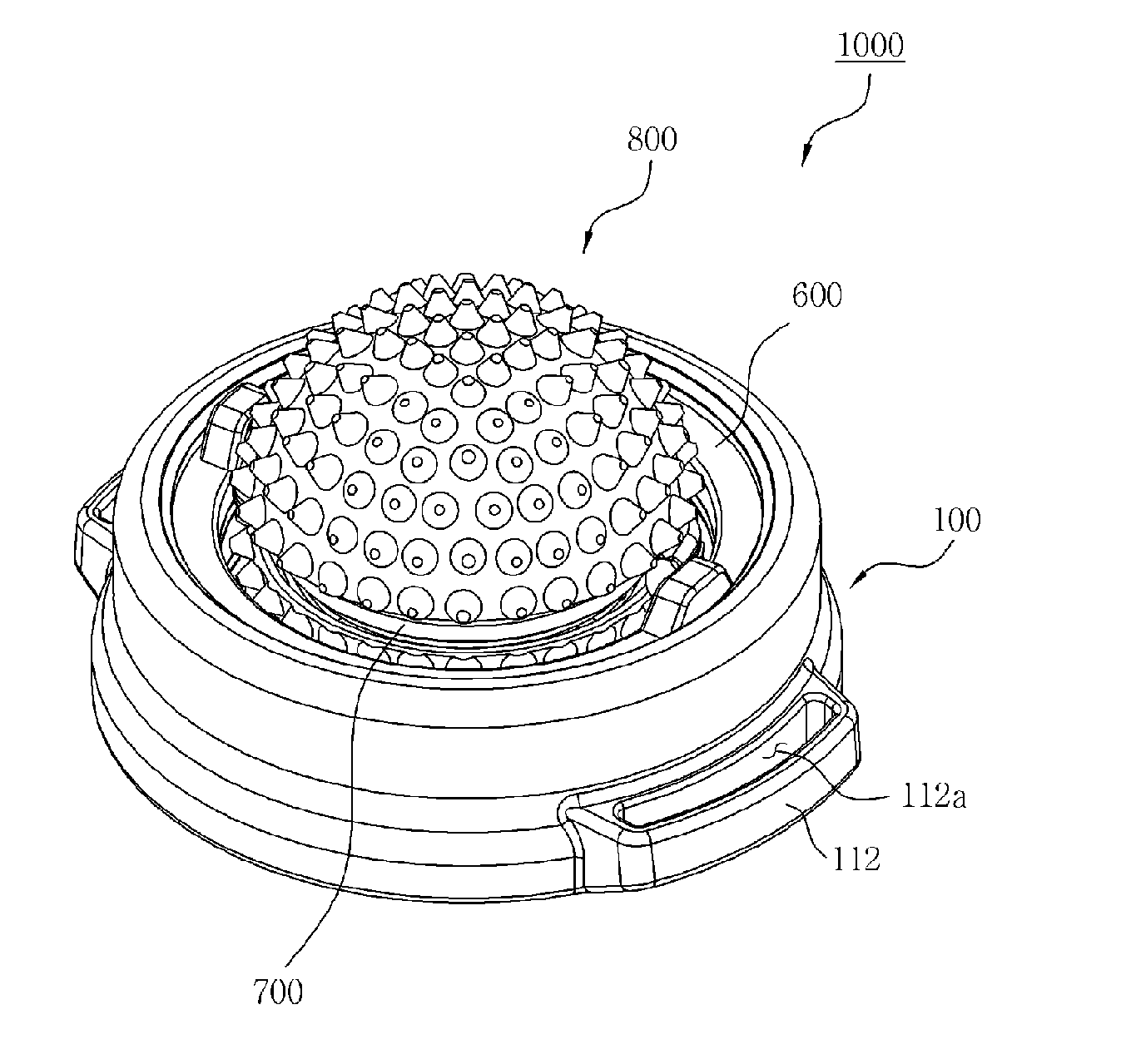
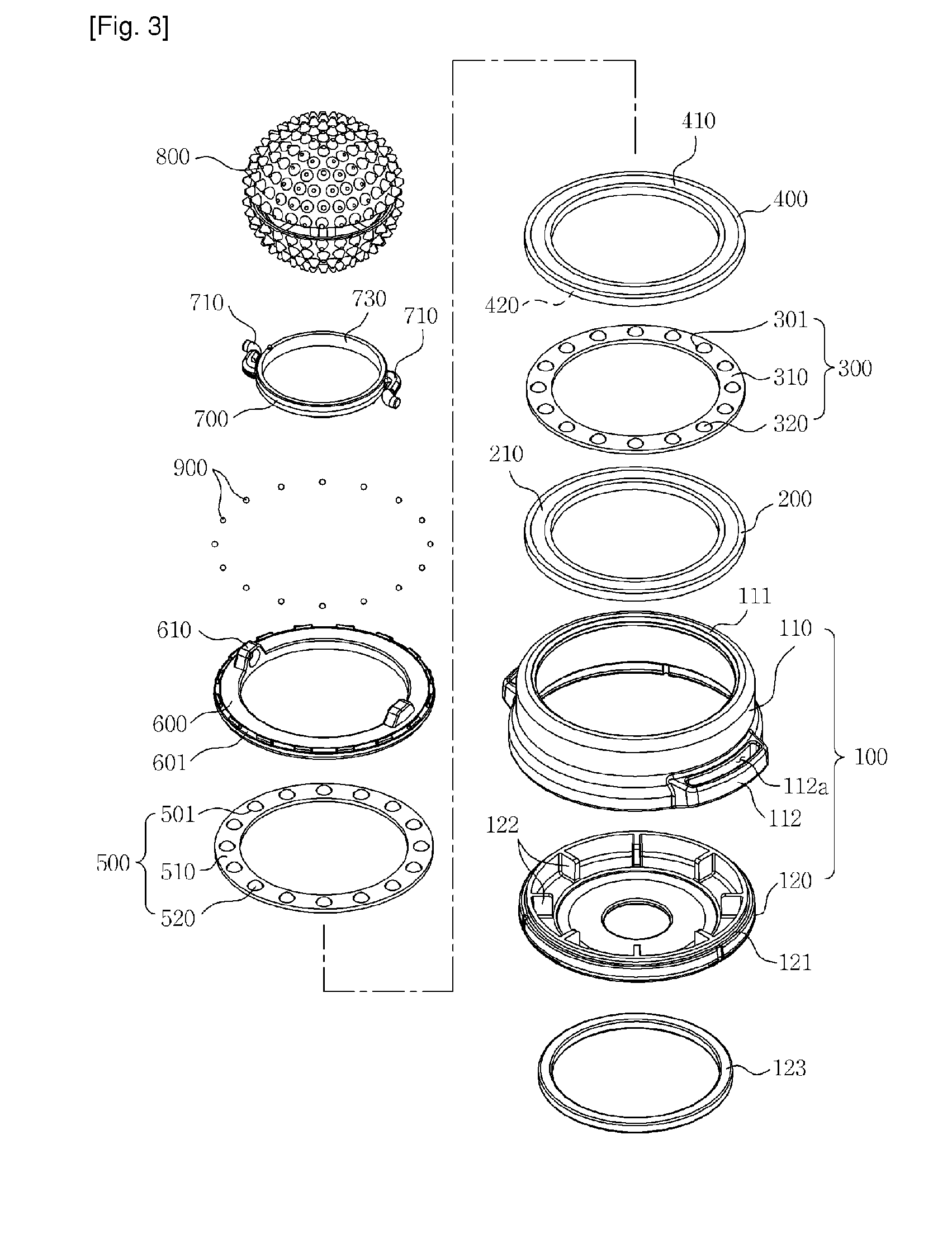
[0028]As shown, a ball acupressure device 1000 according to the present invention comprises a housing body 100, a fixed ring 200 placed on the bottom of the housing body 100, a first bearing 300 provided on the fixed ring 200, a first rotating ring 400 rollably placed on the top of the first bearing 300, a second bearing 500 disposed on a curved groove 410 formed in the circumferential direction of the first rotating ring 400, a second rotating ring 600 rollably placed on the top of the second bearing 500, a clamp 700 rotatably connected to the second rotating ring 600 and rotatably supporting an acupressure part 800, which will be described later, and the acupressure part 800 having the form of a ball freely rotated by the clamp 700 and including a plurality of acupressure pins 801 projecting in the circumferential direction.

[0029]First, the housing body 100 ...


PUM


Abstract

The present invention relates to a ball acupressure device capable of stably fixing internal components and at the same time, performing smooth rotary functions. The invention comprises: a housing body having an opening on the upper part thereof; a fixed ring which is arranged in a state of being placed on the bottom of the housing body; a first bearing which is arranged on the fixed ring; a first rotary ring which is arranged on the first bearing; a second bearing which is arranged on the first rotary ring; a second rotary ring which is arranged on the second bearing to allow a rolling rotation thereon; an acupressure part which is accommodated in the inside part the first rotary ring and the second rotary ring, and in which a plurality of protrusive acupressure pins are formed on the outer side thereof; and a clamp which supports the acupressure part to enable rotation, and at the same time enables rotation on the second rotary ring, wherein an end that prevents separation curves to the inside of the opening and is formed on the upper rim of the housing body, and a ball bearing is interposed between the end that prevents separation and the second rotary ring.

Description

TECHNICAL FIELD[0001]The present invention relates to a ball acupressure device, and particularly to, a ball acupressure device which can stably secure internal components and, at the same time, perform smooth rotation.BACKGROUND ART[0002]In general, an acupressure device is an instrument that promotes blood circulation in such a manner that projections projecting outward intensively press a specific area of the body.[0003]Recently, various types of instruments capable of maximizing the effect of acupressure have been disclosed. As a typical example thereof, an acupressure device provided with an acupressure part in the form of a ball disclosed in Korean Patent No. 0710516 (hereinafter, referred to as “prior art”) will be schematically described.[0004]As shown in FIG. 1, an acupressure device 100 according to the prior art comprises an open hollow housing 110, a bearing 130 provided in the circumferential direction in the housing 110, a lower ring 120 and an upper ring 140 rollably ...

Claims


Application Information

Patent Timeline
Patent Type & Authority Applications(United States)
IPC IPC(8): A61H15/00
CPCA61H15/00A61H39/04A61H2015/0042A61H2201/1695A61H15/0092G09F23/00A61H2201/169
Inventor JUNG, JIN SANG
Owner KWANG ZIN
Learn More