
Ram air turbine with integrated heat exchanger

Active Publication Date: 2013-03-21
GENERAL ELECTRIC CO
View PDF3 Cites 14 Cited by
  • Summary
  • Abstract
  • Description
  • Claims
  • Application Information

AI Technical Summary

Benefits of technology

The patent is for a system that generates electricity in an aircraft when exposed to air outside the plane. It includes a turbine with blades and a shaft, a gearbox with a speed-increasing gear train, a generator, and a heat exchanger to cool the system. The system is designed to efficiently convert the energy of the airstream into electrical power.

Problems solved by technology

The higher power generators, including the gearbox, tend to generate sufficient heat to make it impossible to cool solely by the airstream and use liquid cooling systems, including a heat exchanger, which projects into the airstream.

Method used


Image

  • Ram air turbine with integrated heat exchanger
  • Ram air turbine with integrated heat exchanger
  • Ram air turbine with integrated heat exchanger

Examples


Embodiment Construction

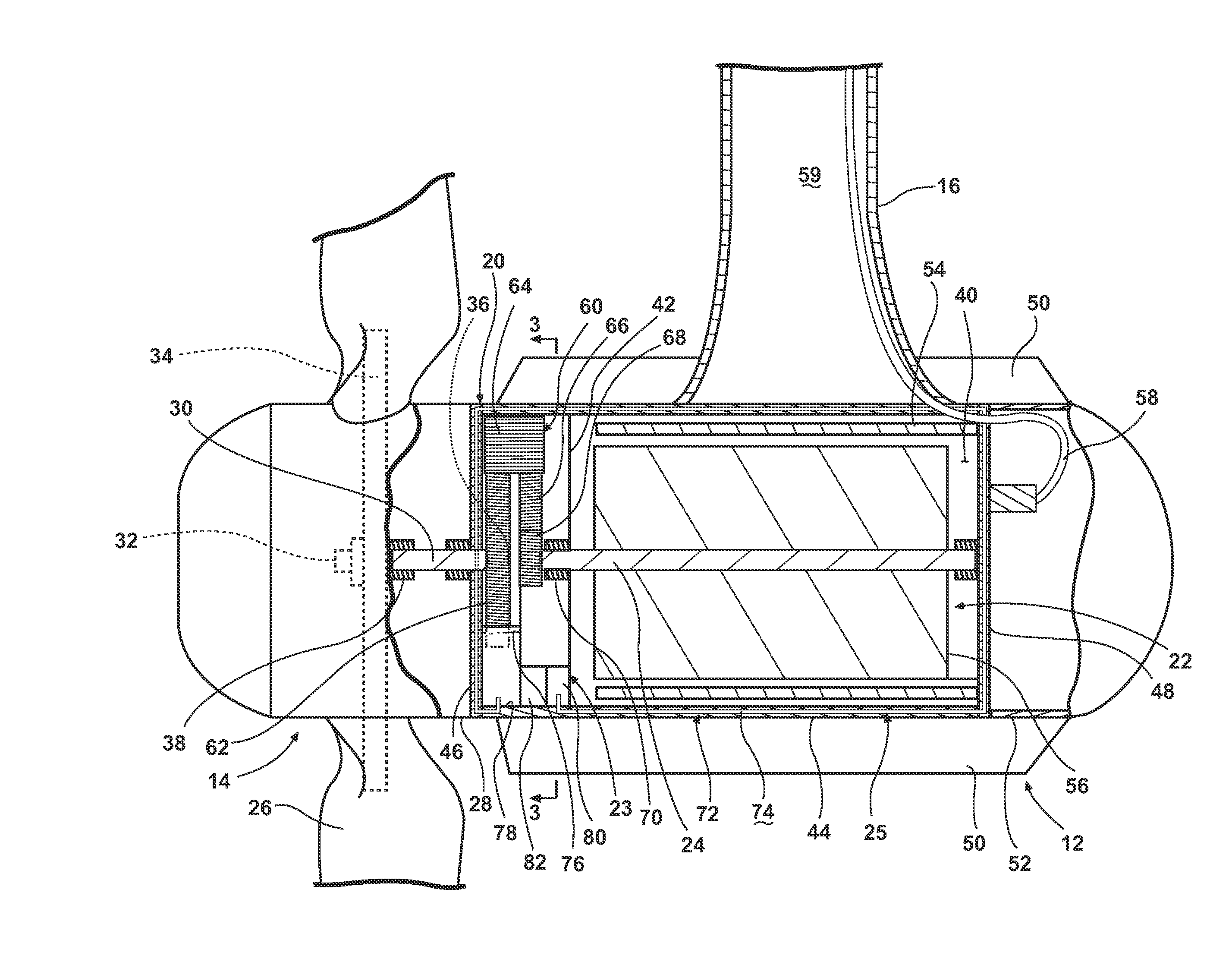
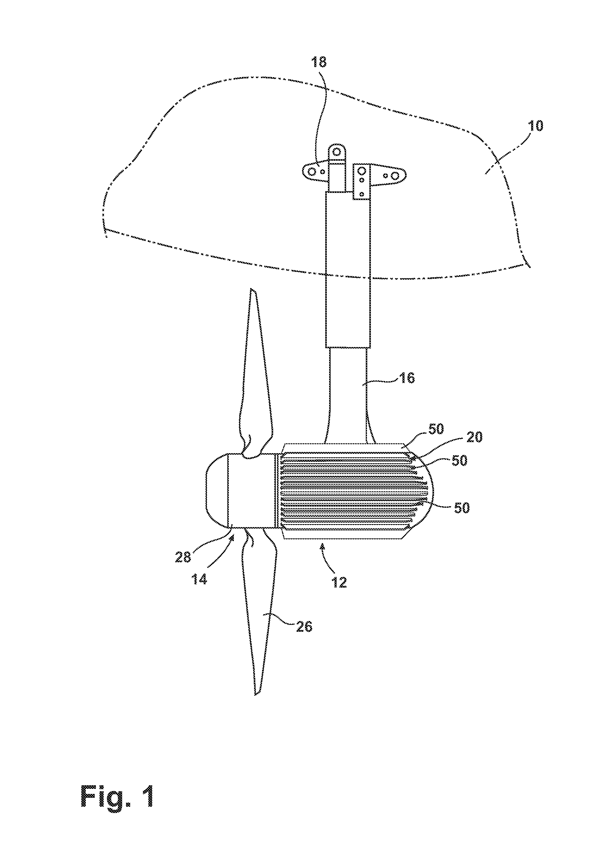
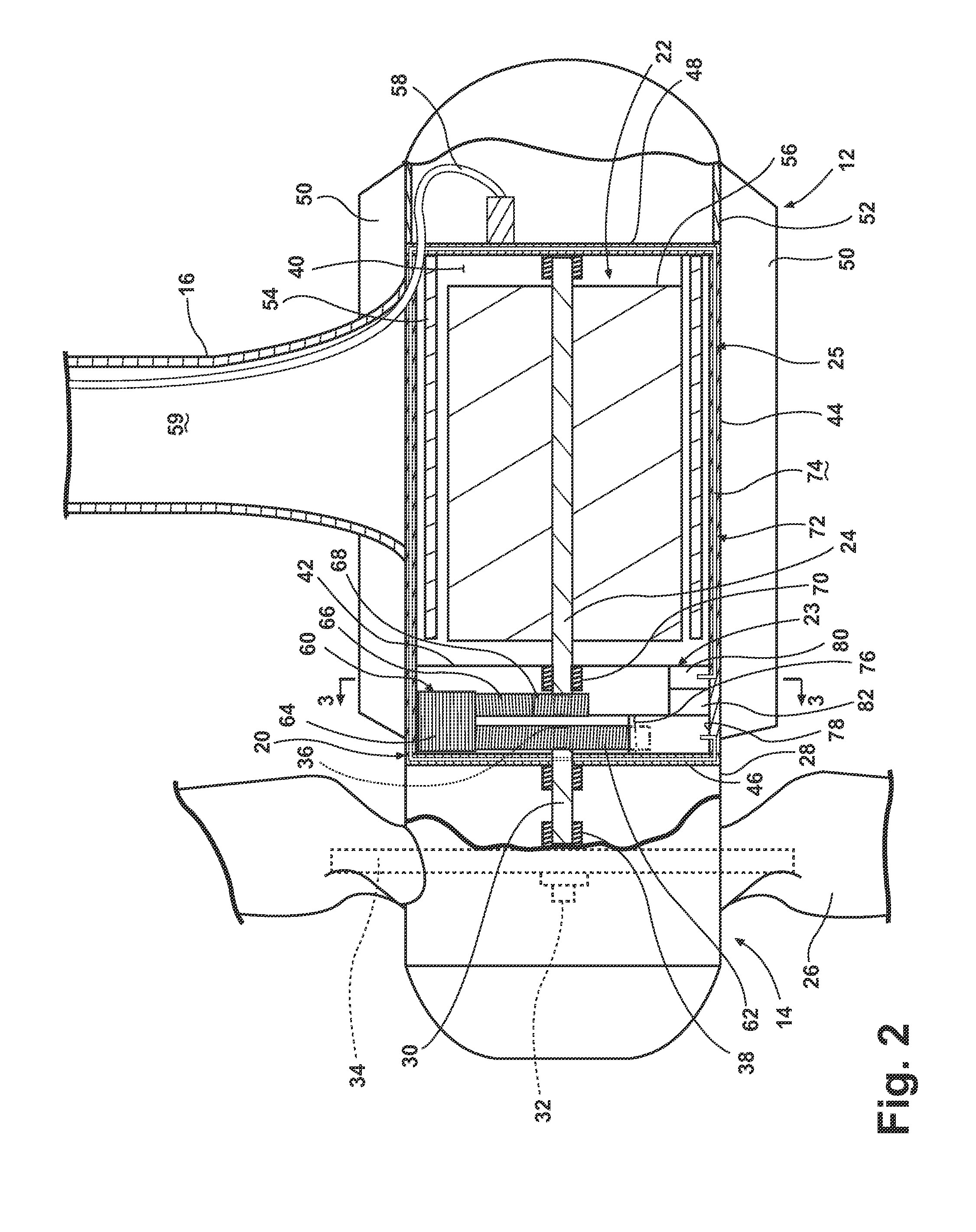
[0010]As illustrated in FIG. 1, an aircraft 10 may include a RAT system 12 for generating electrical power for the aircraft 10 when the RAT system 12 is exposed to the airstream exterior of the aircraft 10. The RAT system 12 may include a RAT 14, which may be suspended from the aircraft 10 by a strut 16 and mounting assembly 18. The RAT 14 may be stored within a suitable compartment in the fuselage or wing of the aircraft 10 and may be deployed quickly and easily by moving the strut 16 relative to the mounting assembly 18, thereby moving the RAT system 12 to an exposed position within the air stream flowing past the aircraft 10. As illustrated in FIG. 2, the RAT 14 includes a housing 20 in which are located an electrical generator 22, a gearbox 23 having a gearbox output element 24, and an integrated heat exchanger 25. A turbine in the form of multiple blades 26 projecting from a rotary hub 28 is provided on one end of the housing 20. Although only two blades 26 have been shown in t...


PUM


Abstract

A ram air turbine system for generating electrical power in an aircraft when the system is exposed to an airstream exterior of the aircraft. The ram air turbine system includes a turbine, a housing defining an interior, a gearbox having a speed-increasing gear train, and a generator.

Description

BACKGROUND OF THE INVENTION[0001]Ram Air Turbine (RAT) systems are used in contemporary aircraft as emergency or supplemental power systems. They typically have a turbine, with a rotating hub and a plurality of blades, operably coupled to a generator to provide the driving source for the generator. Initially in flight they are stowed in a compartment of the aircraft fuselage, covered by a compartment door. When needed as a source of emergency or supplemental power, the RAT system is deployed from the fuselage into the surrounding airstream, which drives the blades to rotate the generator to extract energy from the airstream.[0002]As power requirements for aircraft systems increase, the power generation capabilities of RAT systems continue to increase. Higher power generators tend to be configured to rotate at speeds greater than the rotational speed of the turbine by utilizing a gearbox between the turbine and the generator. The higher power generators, including the gearbox, tend t...

Claims


Application Information

Patent Timeline
IPC IPC(8): F01D15/12
CPCB64D41/007F03D9/00Y02T50/44Y02E10/722F05B2220/31F03D9/25F03D9/32F03D15/10F03D80/60Y02E10/72Y02E10/728Y02T50/40
Inventor TANEJA, DINESH NATHLAYER, JOHN ANDREW
Owner GENERAL ELECTRIC CO
Learn More