
Partially reflecting multilayer optical films with reduced color

a multi-layer optical film and color reduction technology, applied in the field of optical films, can solve the problems of undesired perceived color, imperfect layer thickness control, design and manufacture of polymeric multi-layer optical films, etc., and achieve the effect of high frequency variability and high frequency variability

Active Publication Date: 2013-03-14
3M INNOVATIVE PROPERTIES CO
View PDF0 Cites 31 Cited by
  • Summary
  • Abstract
  • Description
  • Claims
  • Application Information

AI Technical Summary

Benefits of technology

This patent text describes a new invention and its technical effects. The details of the invention can be found in the attached claims. The patent text should be followed without limiting the subject matter.

Problems solved by technology

Thus, as already mentioned above, one challenge faced by designers and manufacturers of polymeric multilayer optical films that are intended to be both (1) partially reflecting along a principal axis and (2) broadband (i.e., intended to provide partial reflectivity over a broad wavelength range) is unintended and undesired perceived color resulting from imperfect layer thickness control.
In practice, multilayer optical films and microlayer packets can exhibit spatial non-uniformities such that spectral peaks and valleys shift slightly in wavelength from one area or place on the film or packet to the next.
Even when such spatial non-uniformities result in another area of the construction at which the respective spectral peaks and valleys of the different films or packets do not tend to cancel each other, we have found that the color of such non-optimal areas typically increases by only a modest amount, such that the overall construction may still have a reduced color on average, where the average may include a spatial average over the useful area of the film construction.
But even though the disclosed multi-packet designs are typically less efficient from an optical standpoint than single packet designs, we have found that they can provide better overall spectral uniformity across the wavelength range when considering the entire useable area of the film body.

Method used


Image

  • Partially reflecting multilayer optical films with reduced color
  • Partially reflecting multilayer optical films with reduced color
  • Partially reflecting multilayer optical films with reduced color

Examples


Embodiment Construction

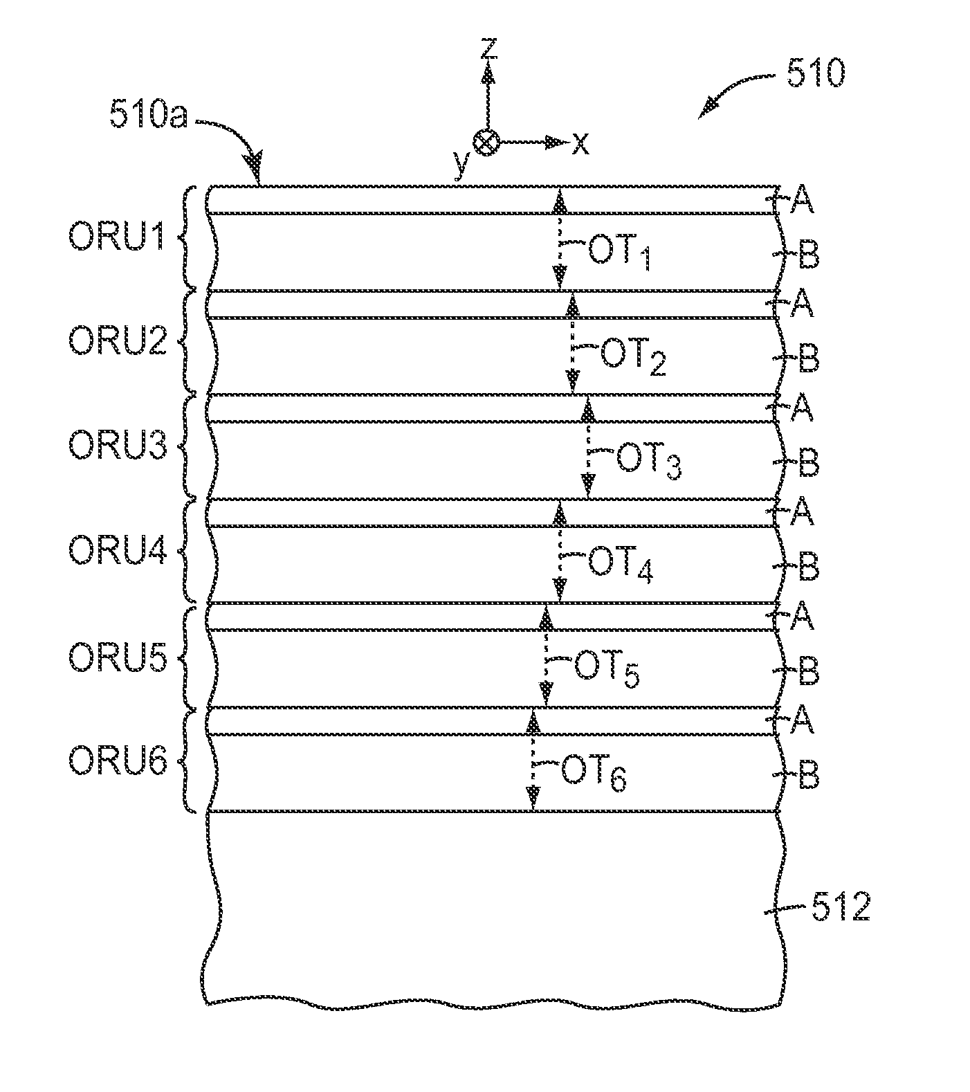
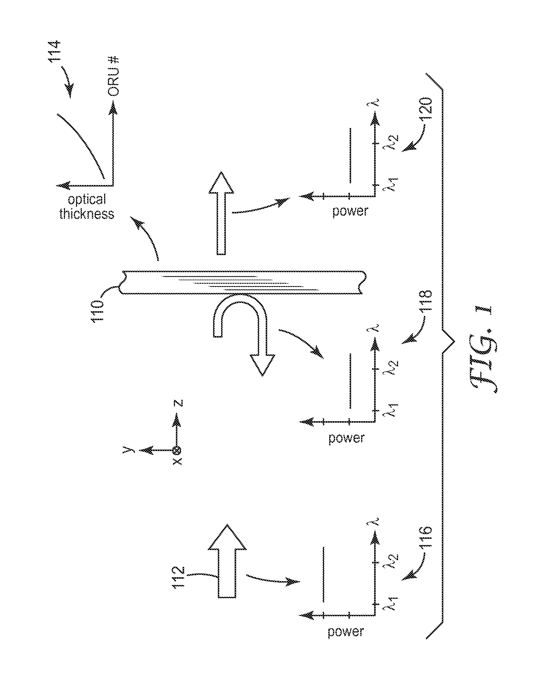
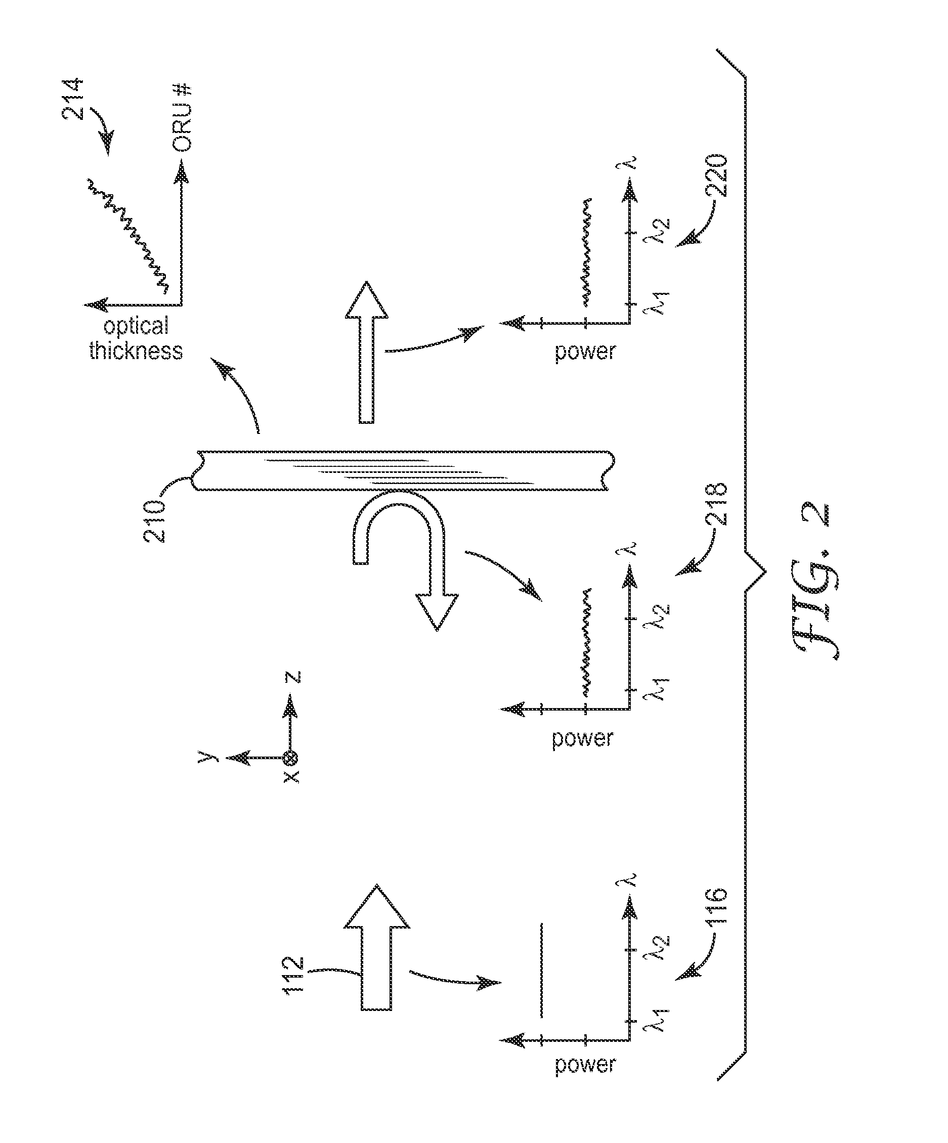
[0039]As mentioned above, one challenge faced by designers and manufacturers of polymeric multilayer optical films that are intended to be both (1) partially reflecting along a principal axis at normal and oblique angles and (2) broadband (i.e., intended to provide partial reflectivity over a broad wavelength range) is unintended and undesired color resulting from imperfect layer thickness control. Such undesired color is typically manifested as relatively high frequency variability in the optical transmission and reflection spectra, the high frequency variability being directly associated with deviations in the thicknesses of the microlayers (stated more accurately, deviations in the optical thicknesses of optical repeat units of microlayers) from their ideal or target values. This challenge facing manufacturers and designers of partially reflecting broadband multilayer optical films will now be explained with reference to FIGS. 1-3. For purposes of these figures, for simplicity, t...


PUM

PropertyMeasurementUnit
wavelength rangeaaaaaaaaaa
wavelengthaaaaaaaaaa

Abstract

A multilayer optical film body includes a first and second packet of microlayers. Each packet partially transmits and partially reflects light over an extended wavelength range, such as the visible region, for normally incident light polarized along a first principal axis of the film body. In combination, the first and second packets have an intermediate reflection and transmission (e.g. 5-95% internal transmission, on average) for the normally incident light, and similar intermediate reflection / transmission (e.g. 10-90% internal transmission, on average) for oblique light. The packets are laminated or otherwise connected so that light can pass through the packets sequentially. In at least a first test area of the film body, a high frequency spectral variability of the combination of packets is less than a high frequency spectral variability of the first packet by itself, and may also be less than a high frequency spectral variability of the second packet by itself.

Description

FIELD OF THE INVENTION[0001]This invention relates generally to optical films whose reflection and transmission characteristics are determined in large part by constructive and destructive interference of light reflected from interfaces between microlayers within the film, with particular application to such films that partially reflect and partially transmit light over an extended wavelength range for a given incidence condition. The invention also relates to associated articles, systems, and methods.BACKGROUND[0002]Multilayer optical films are known. Such films typically incorporate a large number of very thin layers of different light transmissive materials, the layers being referred to as microlayers because they are thin enough so that the reflection and transmission characteristics of the optical film are determined in large part by constructive and destructive interference of light reflected from the layer interfaces. Depending on the amount of birefringence (if any) exhibite...

Claims


Application Information

Patent Timeline
Patent Type & Authority Applications(United States)
IPC IPC(8): G02B27/28G02B27/14B32B7/02B29D11/00B29C47/00B29C48/08B32B7/023
CPCG02B5/285G02B5/305G02B27/142G02B27/144B29C47/0057Y10T156/10B32B7/02G02B27/141G02B27/283B29C47/0021B29D11/0073G02B5/3041G02B27/1006B32B7/023B29C48/08B29C48/0018G02B5/20G02B5/30G02B27/10G02B5/3066
Inventor WEBER, MICHAEL F.STOVER, CARL A.
Owner 3M INNOVATIVE PROPERTIES CO
Learn More