Lamp casing structure
a technology for lamp casings and lamps, applied in the field of lamp casings, can solve the problems of unfavorable lighting protection, unfavorable lighting protection, and inability to use different lamps in different models, etc., and achieve the effects of reducing assembling and installation costs, improving applicability and practicality, and facilitating installation
- Summary
- Abstract
- Description
- Claims
- Application Information
AI Technical Summary
Benefits of technology
Problems solved by technology
Method used
Image


Examples
embodiment 1
Preferred Embodiment 1
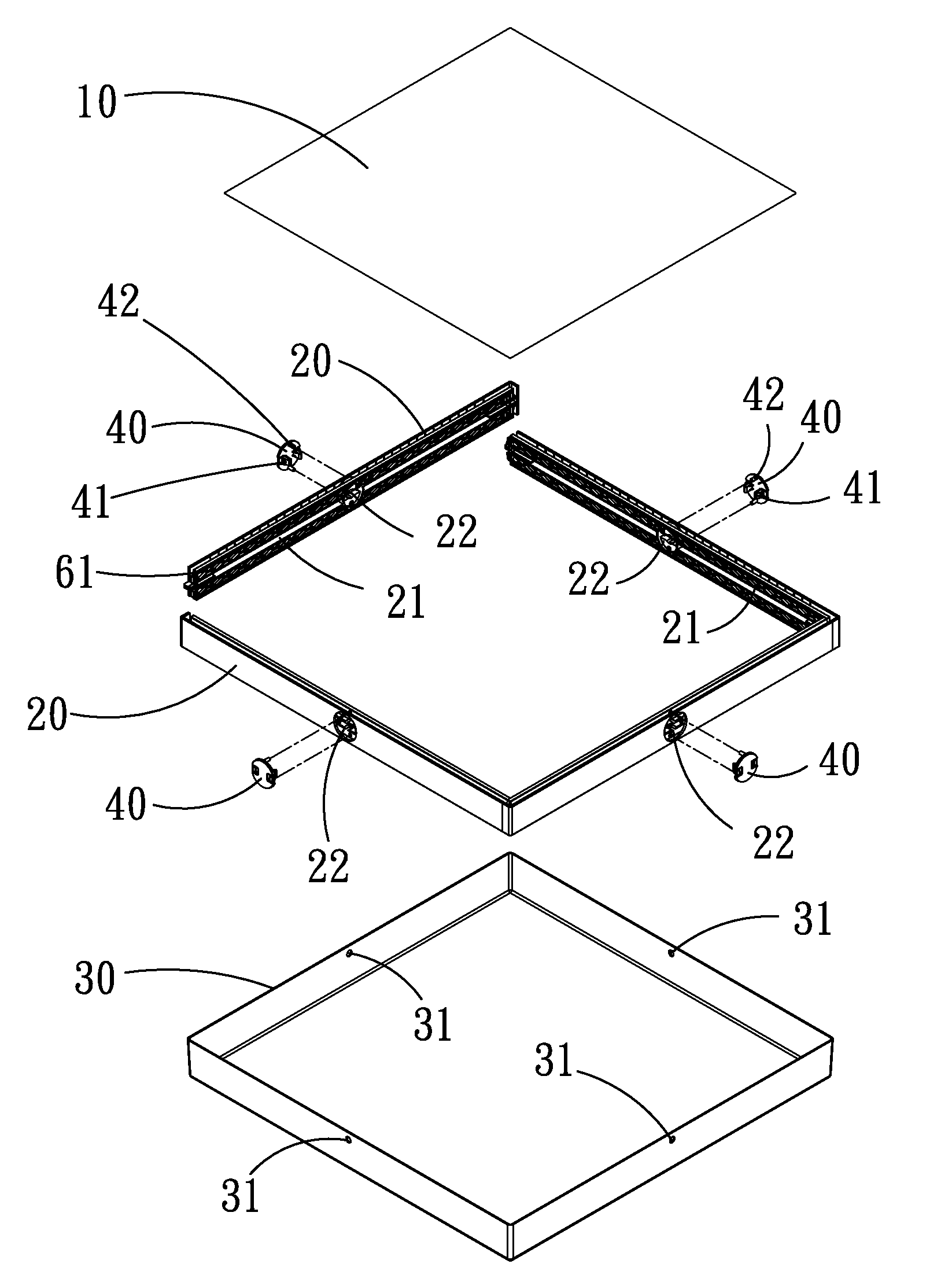
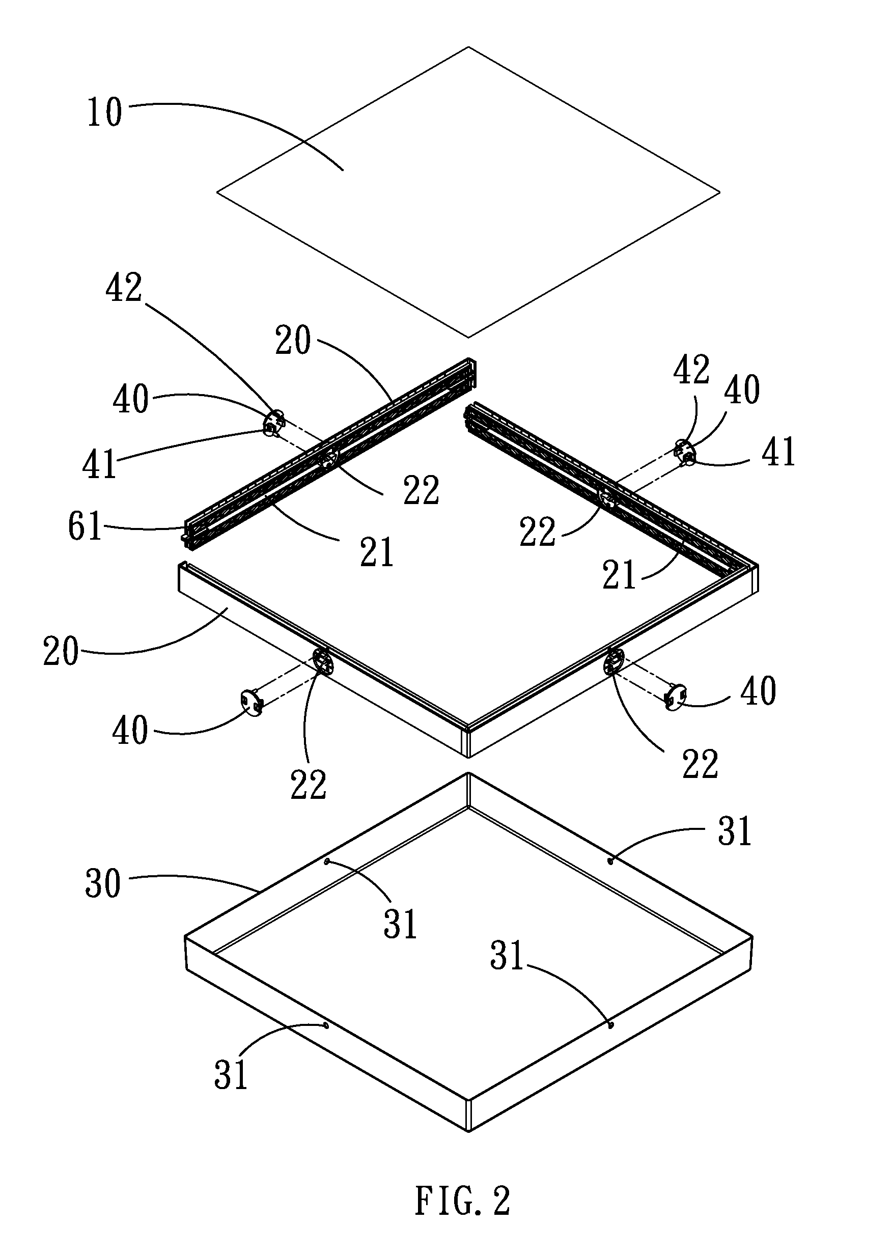
[0030]With reference to FIGS. 1 and 2 for a perspective view and an exploded view of a lamp casing structure in accordance with a first preferred embodiment of the present invention respectively, the present invention provides a shielding effect for a light board 10 of a lamp, and further uses an assembly with a frame strip 20, a first transparent cover 30 and a fastener 40 to provide an easy assembling and installation and different ways of installing the lamp casing structure. The lamp casing structure of the present invention comprises: a predetermined quantity of frame strips 20, at least one first transparent cover 30, and a predetermined quantity of fasteners 40.
[0031]The frame strips 20 are coupled to one another and disposed around the periphery of the first transparent cover, and each frame strip 20 includes an insert slot 21 formed on an internal side of the frame strip 20 for embedding the light board 10, and a latch portion 22 formed at a middle sec...
embodiment 2
Preferred Embodiment 2
[0037]With reference to FIGS. 3 and 4 for a lamp casing structure in accordance with the second preferred embodiment of the present invention, the lamp casing structure comprises a predetermined quantity of frame strips 20, a first transparent cover 30, a second transparent cover 50, and a predetermined quantity of fasteners 40.
[0038]The frame strip 20 are coupled with one another and disposed around the periphery of the first transparent cover, and each frame strip 20 includes an insert slot 21 formed on an internal side of the frame strip 20 for embedding the light board 10, and each frame strip 20 includes a latch portion 22 disposed at the middle section of the frame strip 20.
[0039]The first transparent cover 30 is the main light emitting surface of the lamp casing structure, and the first transparent cover 30 includes a latch portion 31 disposed at the periphery of the first transparent cover 30 and corresponding to the middle section of the frame strip 20...
embodiment 3
Preferred Embodiment 3
[0043]With reference to FIGS. 5 and 6 for a lamp casing structure in accordance with the third preferred embodiment of the present invention, the lamp casing structure comprises a predetermined quantity of frame strips 20, a first transparent cover 30, a dust cover 60, and a predetermined quantity of fasteners 40.
[0044]The frame strip 20 are coupled with one another and disposed around the periphery of the first transparent cover, and each frame strip 20 includes an insert slot 21 formed on an internal side of the frame strip 20 for embedding the light board 10, and each frame strip 20 includes a latch portion 22 disposed at the middle section of the frame strip 20.
[0045]The first transparent cover 30 is the main light emitting surface of the lamp casing structure, and the first transparent cover 30 includes a latch portion 31 disposed at the periphery of the first transparent cover 30 and corresponding to the middle section of the frame strip 20.
[0046]The dust...
PUM
 Abstract
Description
Claims
Application Information
 - R&D
- Intellectual Property
- Life Sciences
- Materials
- Tech Scout
- Unparalleled Data Quality
- Higher Quality Content
- 60% Fewer Hallucinations
Browse by: Latest US Patents, China's latest patents, Technical Efficacy Thesaurus, Application Domain, Technology Topic, Popular Technical Reports.
© 2025 PatSnap. All rights reserved.Legal|Privacy policy|Modern Slavery Act Transparency Statement|Sitemap|About US| Contact US: help@patsnap.com