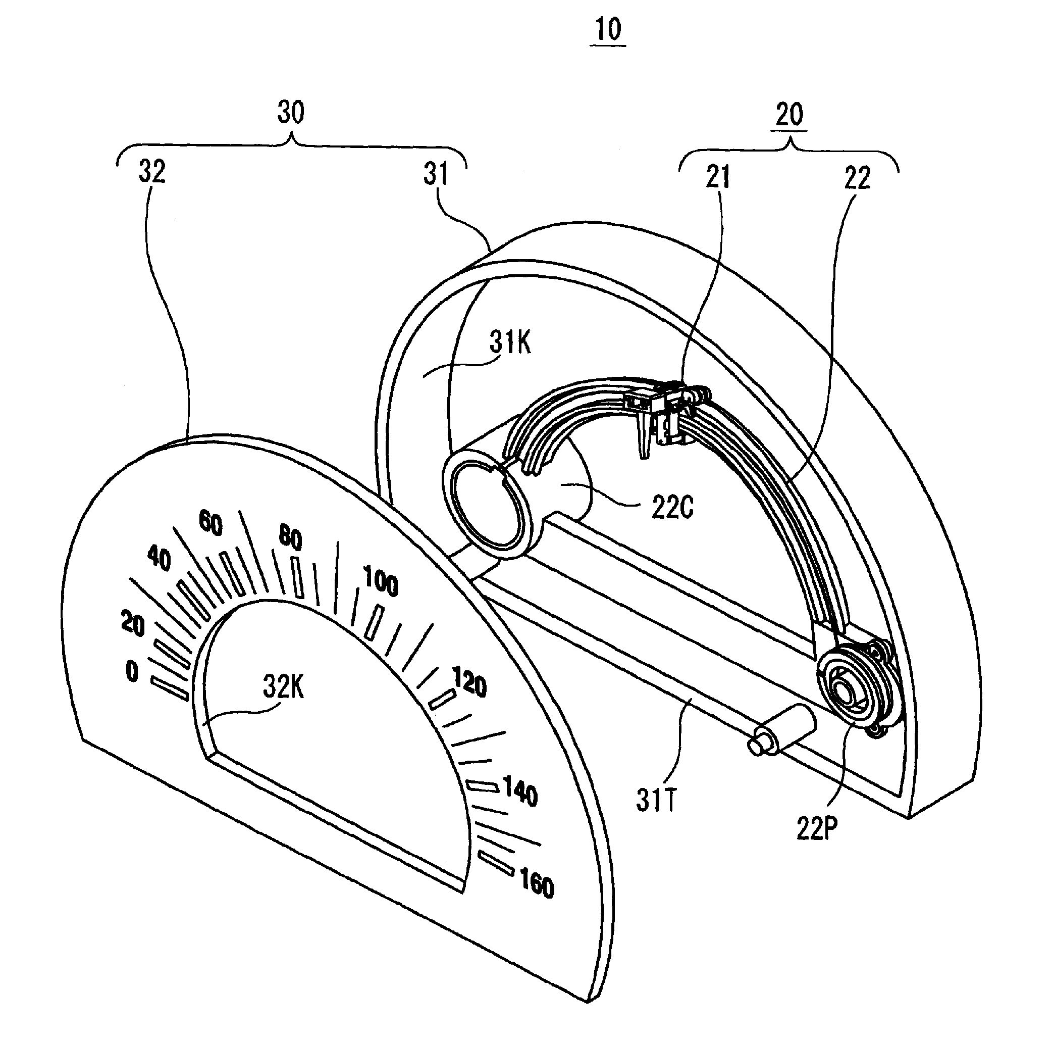
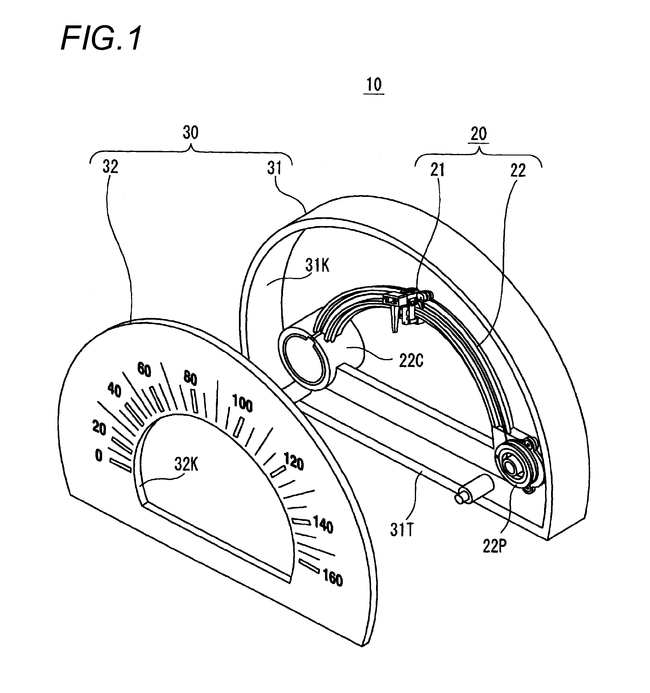
Center-less pointer type display apparatus
a display apparatus and centerless technology, applied in the direction of measurement apparatus components, instruments, measurement devices, etc., can solve the problems of insufficient stably carrying the pointer, the reduction of friction resistance is not suitable, etc., to prevent the friction between the pulley and the guide rail from increasing, and the effect of stably carrying
- Summary
- Abstract
- Description
- Claims
- Application Information
AI Technical Summary
Benefits of technology
Problems solved by technology
Method used
Image
Examples
first embodiment
[0103]While the pointer moving device according to the invention solving the problems of the related art invention is described above, the related art invention additionally has the following problems.
[0104]>
[0105]The support member 210Z shown in FIG. 8 is constituted such that the first support member 210A and the second support member 210B sandwich the coil spring 210S and are integrally fitted to each other. However, when some sort of strong vibration occurs, there is a possibility that the second support member 210B comes off from the first support member 210A, and thereby the second support member 210B falls. When the second support member 210B falls, the entirety of the pointer attachment section finally falls from the guide rail 220R.
[0106]>
[0107]FIGS. 12(A) and 12(B) are schematic views showing an improved example capable of solving the problem of the pointer shown in FIG. 8.
[0108]In FIGS. 12(A) and 12(B), a boss 210H for stopper is formed on the pointer 210C at its upper po...
second embodiment
[0112]The purpose of the second embodiment is to eliminate the above problem, and to provide a pointer moving device capable of preventing an entirety of a pointer attachment section from coming off from a guide rail even in the way of an assembling operation.
[0113]
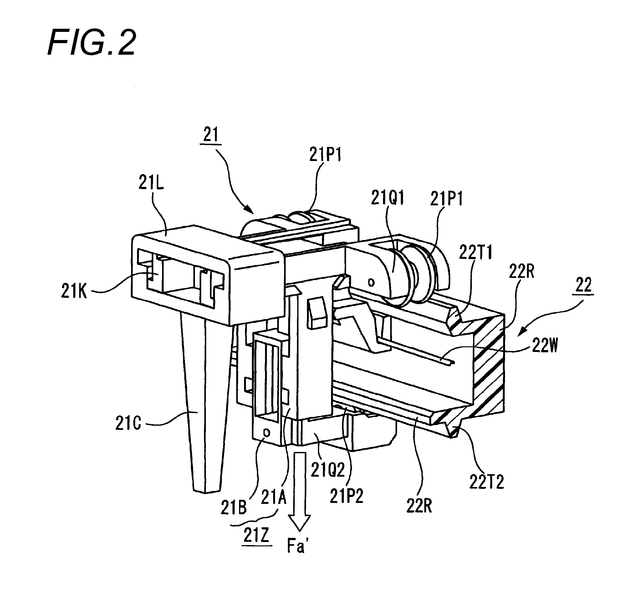
[0114]In FIG. 13 of an exploded perspective view of a pointer moving device according to the second embodiment of the invention and FIG. 14 of a vertical cross-sectional view thereof, a pawl 21N for stopper is formed on the second support member 21B (in FIG. 13) which presses the upper portion of the coil spring 21S. A hole portion 21M for restriction (in FIG. 14) is formed on the first support member 21A at a portion where the hole portion 21M for restriction faces the pawl 21N for stopper in a state in which the first support member 21A (in FIG. 13) adapted to press the lower portion of the coil spring 21S and the second support member 21B are assembled with each other.
[0115]
[0116]With the above, downward moving of the ...
PUM
 Abstract
Description
Claims
Application Information
 - R&D
- Intellectual Property
- Life Sciences
- Materials
- Tech Scout
- Unparalleled Data Quality
- Higher Quality Content
- 60% Fewer Hallucinations
Browse by: Latest US Patents, China's latest patents, Technical Efficacy Thesaurus, Application Domain, Technology Topic, Popular Technical Reports.
© 2025 PatSnap. All rights reserved.Legal|Privacy policy|Modern Slavery Act Transparency Statement|Sitemap|About US| Contact US: help@patsnap.com


