Eureka AIR delivers breakthrough ideas for toughest innovation challenges, trusted by R&D personnel around the world.

Method of controlling a printing device, and a printing device

a printing device and printing technology, applied in printing, other printing devices, etc., can solve the problems of inability to print as desired, inability to detect paper feed errors, and inability to correct media conveyan

Inactive Publication Date: 2013-02-21
SEIKO EPSON CORP
View PDF1 Cites 13 Cited by
  • Summary
  • Abstract
  • Description
  • Claims
  • Application Information

AI Technical Summary

Benefits of technology

The present invention is about a method and device for printing using a recording medium that is shorter than the distance between two conveyance units, which can prevent uneven processing, soiling or damage to the recording medium, and ensure that the print area is accurately aligned. By calculating the remaining distance the recording medium has not been conveyed and adding it to the conveyance process, printing can be completed even if the recording medium is not fed enough. This method also avoids further conveyance deficiencies and ensures desirable printing results.

Problems solved by technology

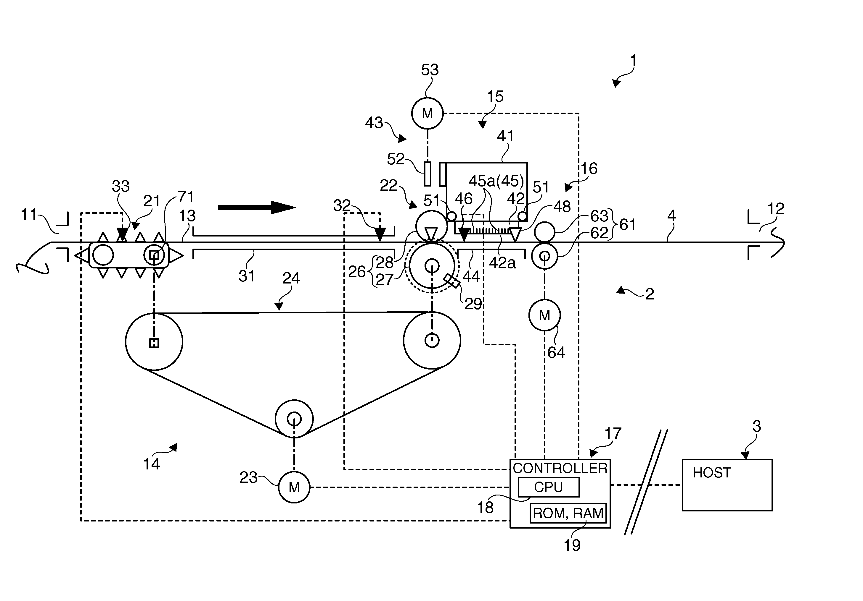
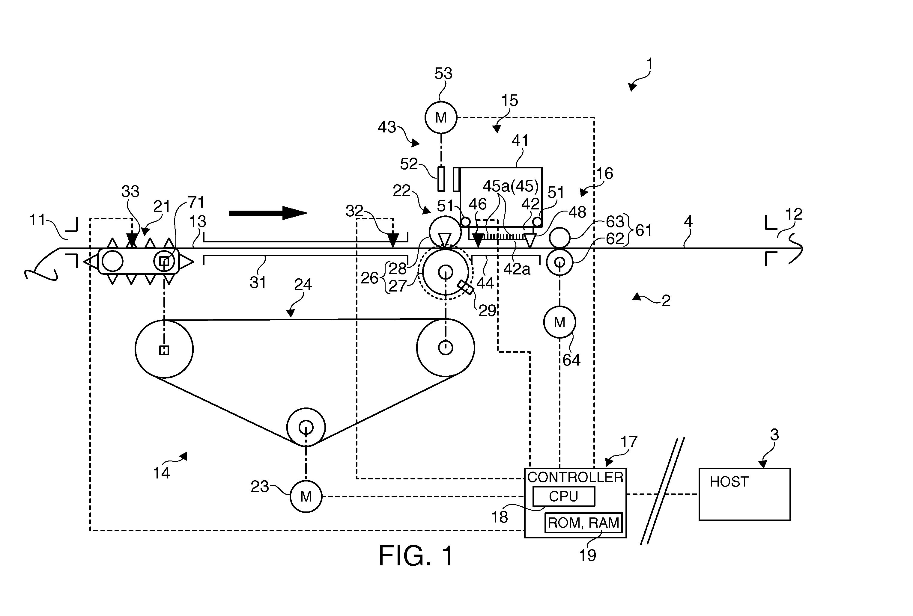
If irregular printing paper that is shorter than the distance between the tractor mechanism and the platen is mistakenly inserted to such a printer according to the related art, the paper cannot be desirably passed between the tractor mechanism and the platen, media conveyance cannot be corrected as described above, and printing as desired is not possible.
If a sensor is not provided near the platen in this case, paper feed errors cannot be detected and problems such as printing directly on the platen or the paper becoming jammed may occur.
This is particularly desirable because printing outside the print area using an inkjet print unit soils the recording medium or the inside of the printer, and damages the platen when using a thermal print unit.

Method used


Image

  • Method of controlling a printing device, and a printing device
  • Method of controlling a printing device, and a printing device
  • Method of controlling a printing device, and a printing device

Examples


second embodiment

[0064]The first control method (FIG. 5A) and second control method (FIG. 5B) of the invention are described next.

first embodiment

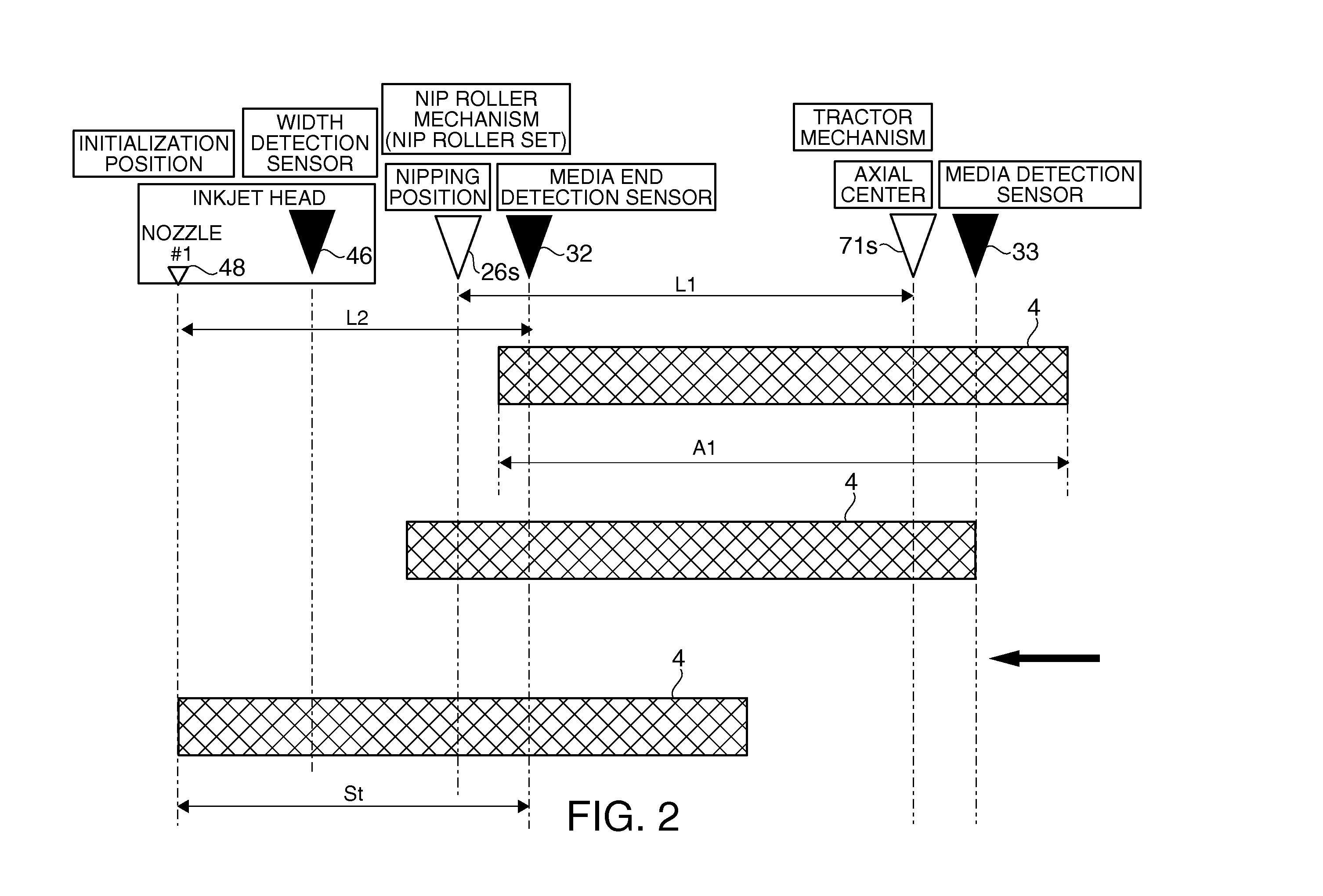
[0065]This control method acquires a second reference step count Sa2, which is the number of conveyance steps (second reference conveyance distance) equal to the distance L4 between the media end detection sensor 32 and width detection sensor 46 (second reference distance acquisition unit). As in conveyance control in the first embodiment, this control method is based on the width detection sensor 46 detecting the leading end. The second reference distance acquisition unit is rendered by the controller 17.

[0066]As shown in FIG. 5A, this first control method counts the actual number of steps (second actual conveyance distance) from detection of the leading end by the media end detection sensor 32 until detection of the leading end by the width detection sensor 46 during the time from the start of recording medium 4 conveyance (S-1) until conveyance stops, and saves this count as the second actual conveyance step count Sb2 (S-2, second actual measurement unit). Conveyance of the recor...


PUM


Abstract

A control method that conveys a recording medium fed from a first conveyance unit a specific number of paper feed steps after the leading end is detected by a first detection unit, and stops conveyance after conveying the leading end of the recording medium passed the second conveyance unit, second detection unit, and print unit to an initial printing position has a reference distance acquisition step that gets a reference number of conveyance steps equal to the distance between the second detection unit and the initial printing position in the specific number of conveyance steps; an actual step count measurement step that measures an actual number of steps the recording medium is conveyed during actual conveyance from detection of the leading end by the second detection unit until conveyance stops; and an evaluation step that determines if paper feed error occurred when conveying the recording medium.

Description

[0001]Priority is claimed under 35 U.S.C. §119 to Japanese Application nos. 2011-177420 filed on Aug. 15, 2011 which is hereby incorporated by reference in their entirety.BACKGROUND[0002]1. Technical Field[0003]The present invention relates to a method of controlling a printing device that stops the recording medium at an initial printing position (start printing position) before the print unit after feeding a recording medium from a first conveyance unit to a second conveyance unit.[0004]2. Related Art[0005]Printers that convey a print medium (recording medium) using a platen (platen roller) disposed opposite a printhead unit, a tractor mechanism located on the upstream side of the platen, and a discharge roller located on the downstream side of the platen, are known from the literature. See, for example, Japanese Unexamined Patent Appl. Pub. JP-A-2000-16656. The printer described in JP-A-2000-16656 adjusts the paper feed distance in steps according to a correction amount previousl...

Claims


Application Information

Patent Timeline
Patent Type & Authority Applications(United States)
IPC IPC(8): B41J29/393
CPCB41J13/0009B41J11/0095
Inventor MASUDA, ICHIMINAKAGAWA, MASAYUKI
Owner SEIKO EPSON CORP
Why Eureka
Eureka Blog
Learn More