Generation plant control apparatus and method

Active Publication Date: 2013-02-21
PSYMETRIX
View PDF3 Cites 13 Cited by
  • Summary
  • Abstract
  • Description
  • Claims
  • Application Information

AI Technical Summary

Benefits of technology

[0039]The first phase angle difference will be compared with a first predetermined threshold phase angle difference such that the corresponding electrical route does not encounter any overload or overvoltage. By determining a second phase angle difference that will be compared with a second predetermined threshold phase angle difference such that t

Problems solved by technology

In electrical power networks comprising renewable generation plants, such as wind power generation plants, network utilisation of the generation plants tends to be low because of conservative assumptions about available power and network loading.
Typically, in a network comprising wind power generation plants, which may include wind farms, the amount of wind generating capacity that is permitted to be connected to the network is limited by the condition in which wind generation is high and network loading is low, which results in worst case power flow into the network and voltage rise.
The electrical route may have a number of technical limits restricting th

Method used


Image

  • Generation plant control apparatus and method
  • Generation plant control apparatus and method
  • Generation plant control apparatus and method

Examples


Example

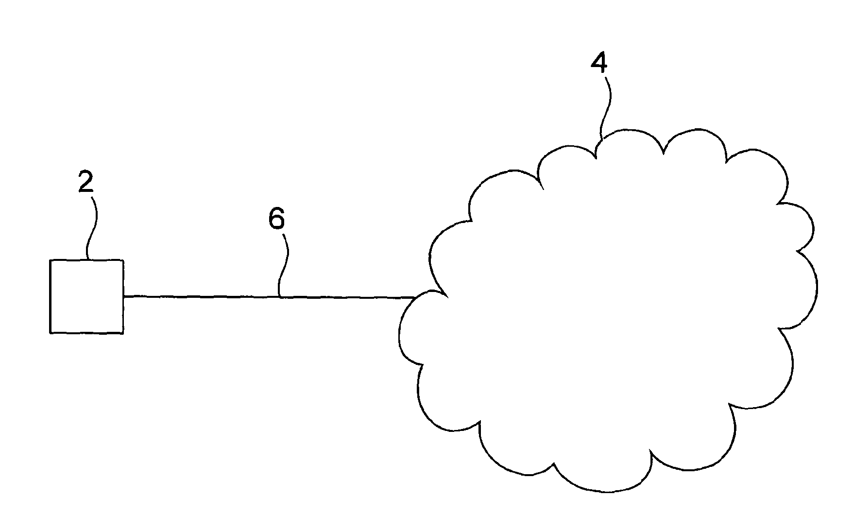
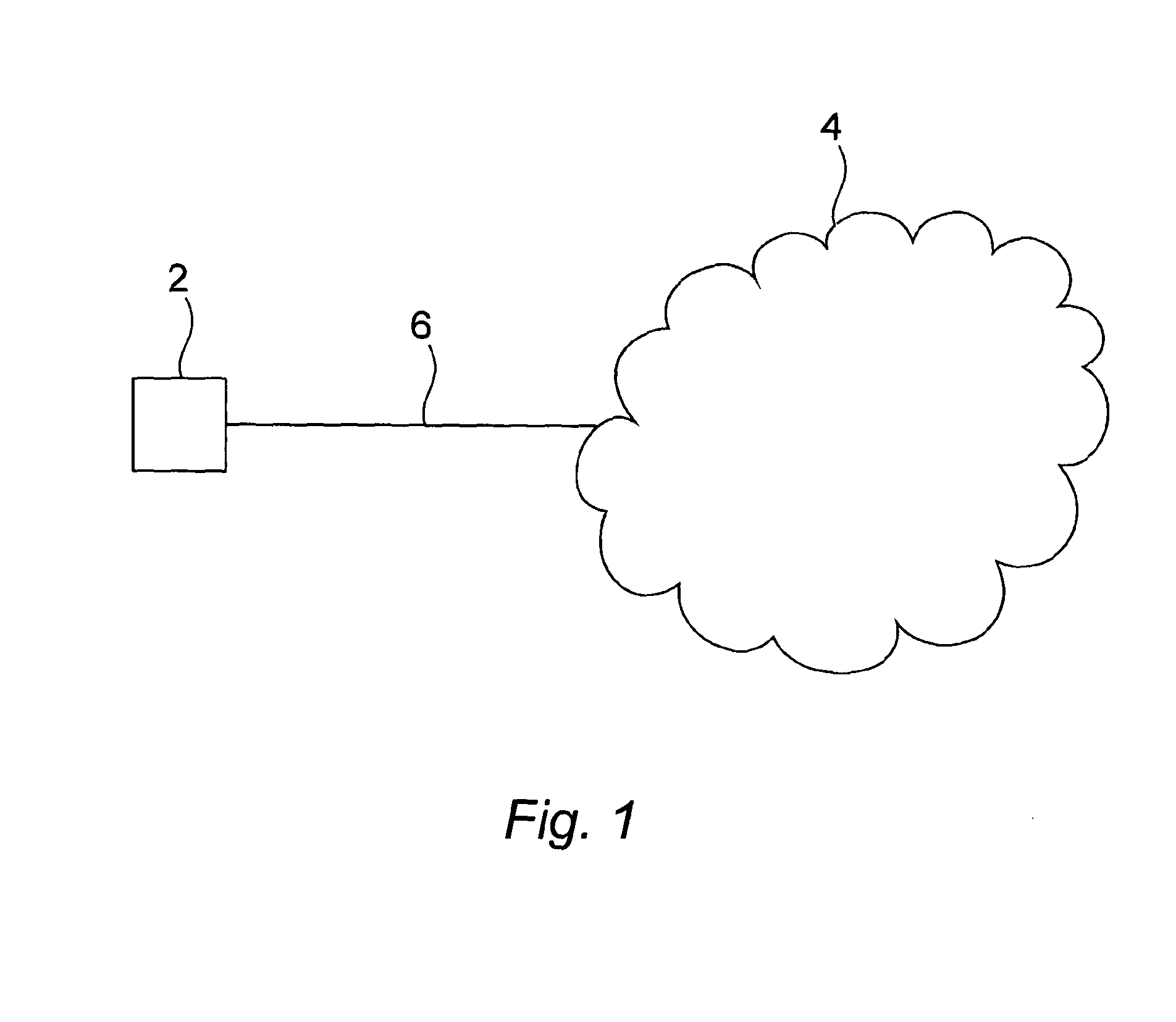
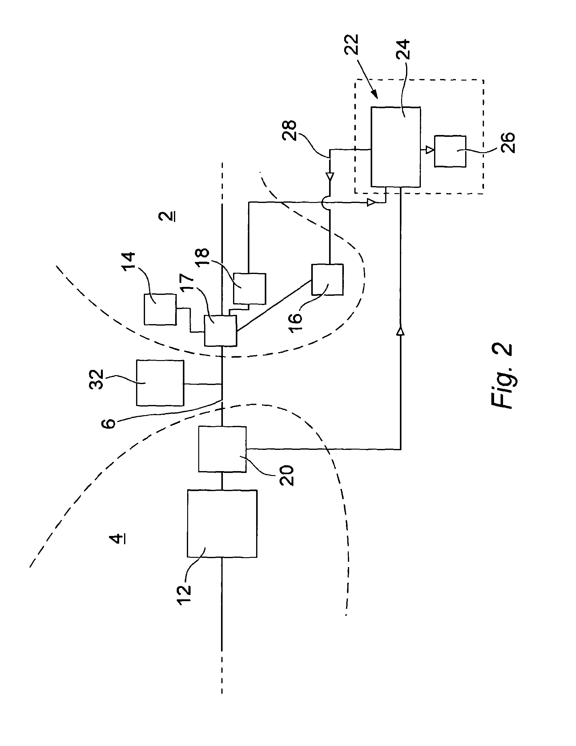
[0086]Referring to FIG. 1, a generation plant 2 is shown connected to a bulk electrical power network 4 by means of an electrical route 6 in accordance with an exemplary embodiment of the invention.

[0087]The bulk electrical power network 4 is the stronger part of the electrical power network to which the electrical route 6 is connected. The limits on the power transfer that the invention addresses are in the electrical route 6. Normally, the electrical route 6 will connect to a higher voltage level in the bulk electrical power network 4 through a transformer (not shown).

[0088]The electrical route 6 is the electrical connection between the generation plant 2 and the bulk electrical power network 4. This can be, for example, a distribution line. There may be several other generation plants and load connections along the route. The electrical route 6 has a number of technical limits to the transfer of power. The invention is intended to increase the feasible energy transfer through the...


PUM


Abstract

A method of controlling an output of a generation plant (2) that is connected to a bulk electrical power network (4) by an electrical route (6). The method comprises determining (31) a phase angle difference between a first phase angle representing a phase angle of a voltage waveform at an output of the generation plant (2) and a second phase angle representing a phase angle of a voltage waveform at a location within the bulk electrical power network (4). The phase angle difference is compared (32) to a threshold phase angle difference that represents a constraint on the electrical route (6). The output of the generation plant (2) is controlled (33, 34) based on the comparison to prevent overloading of the electrical route (6).

Description

FIELD OF THE INVENTION[0001]The present invention relates to an apparatus for and method of providing for control of an electrical generation plant, such as a renewable energy generation plant with a non-firm connection to an electrical grid.BACKGROUND TO THE INVENTION[0002]In electrical power networks comprising renewable generation plants, such as wind power generation plants, network utilisation of the generation plants tends to be low because of conservative assumptions about available power and network loading. Typically, in a network comprising wind power generation plants, which may include wind farms, the amount of wind generating capacity that is permitted to be connected to the network is limited by the condition in which wind generation is high and network loading is low, which results in worst case power flow into the network and voltage rise. The worst case condition particularly affects the area here defined as the electrical route.[0003]As used herein the term ‘genera...

Claims


Application Information

Patent Timeline
IPC IPC(8): H02P9/04
CPCH02J3/1807Y02E40/30H02J3/46
Inventor WILSON, DOUGLAS HARMANOCHOA, LUIS FERNANDO
Owner PSYMETRIX
Why Eureka
Try Eureka