
Mechanical pivot shift measurement to evaluate joints

Active Publication Date: 2013-02-14
RGT UNIV OF CALIFORNIA
View PDF5 Cites 26 Cited by
  • Summary
  • Abstract
  • Description
  • Claims
  • Application Information

AI Technical Summary

Benefits of technology

The patent describes a way to measure the stability of joints like knees using a special test. This test involves applying a known force to the leg and measuring the movement of the knee joint. This information can help diagnose injuries and evaluate the effectiveness of treatment. The apparatus and method can provide a better understanding of joint biomechanics and help with joint replacement surgery. The technology measures joint kinematics by applying a force to move the joint in a way that mimics a common joint injury.

Problems solved by technology

In an ACL deficient knee, abnormal kinematics result in medial meniscus tears and degenerative arthritis.
However, despite the short term success of current procedures, the incidence of osteoarthritis is the same in ACL-deficient and ACL-reconstructed knees, indicating that current reconstruction techniques are not adequate in restoring rotational knee kinematics to their native state.
Failure to restore rotational stability directly correlates with arthritis progression and poor long-term outcomes.
The presence of a positive pivot shift is predictive of osteoarthritis development, failure to return to previous level of play, patient-reported instability, and poor subjective and objective outcomes following ACL reconstruction.
Consequently, it has poor sensitivity and is difficult to reproduce in a clinical or laboratory setting.
Since different joint loading combinations induce distinctive kinematic behavior, the results and their interpretation are often inconsistent between studies, making it difficult to determine the effects of graded knee injuries (ligament and meniscus) and different ACL reconstruction techniques, on rotational stability.

Method used


Image

  • Mechanical pivot shift measurement to evaluate joints
  • Mechanical pivot shift measurement to evaluate joints
  • Mechanical pivot shift measurement to evaluate joints

Examples


experimental examples

III. Experimental Examples

[0046]A. Preliminary Studies.

[0047]1. Manual Pivot Shift Test Versus Mechanical Pivot Shift Apparatus.

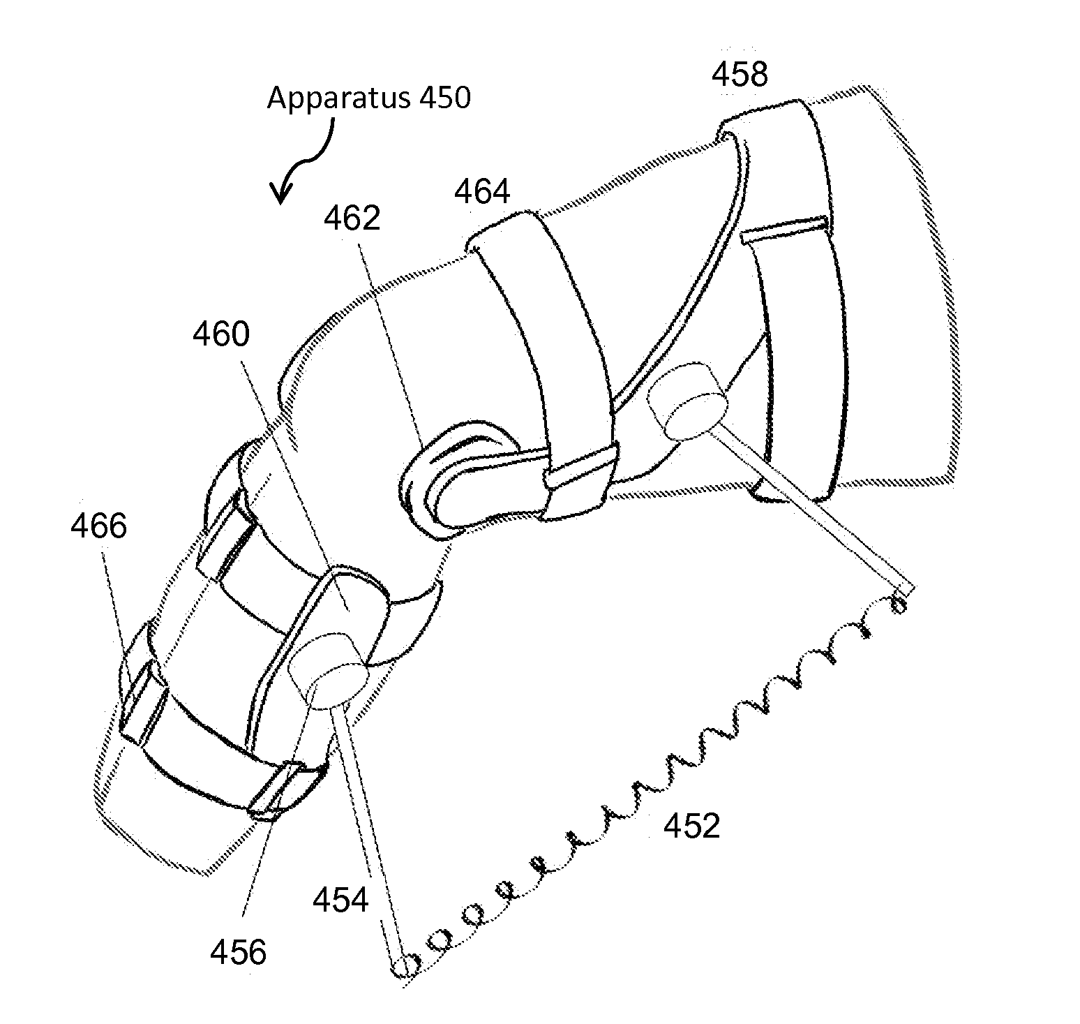
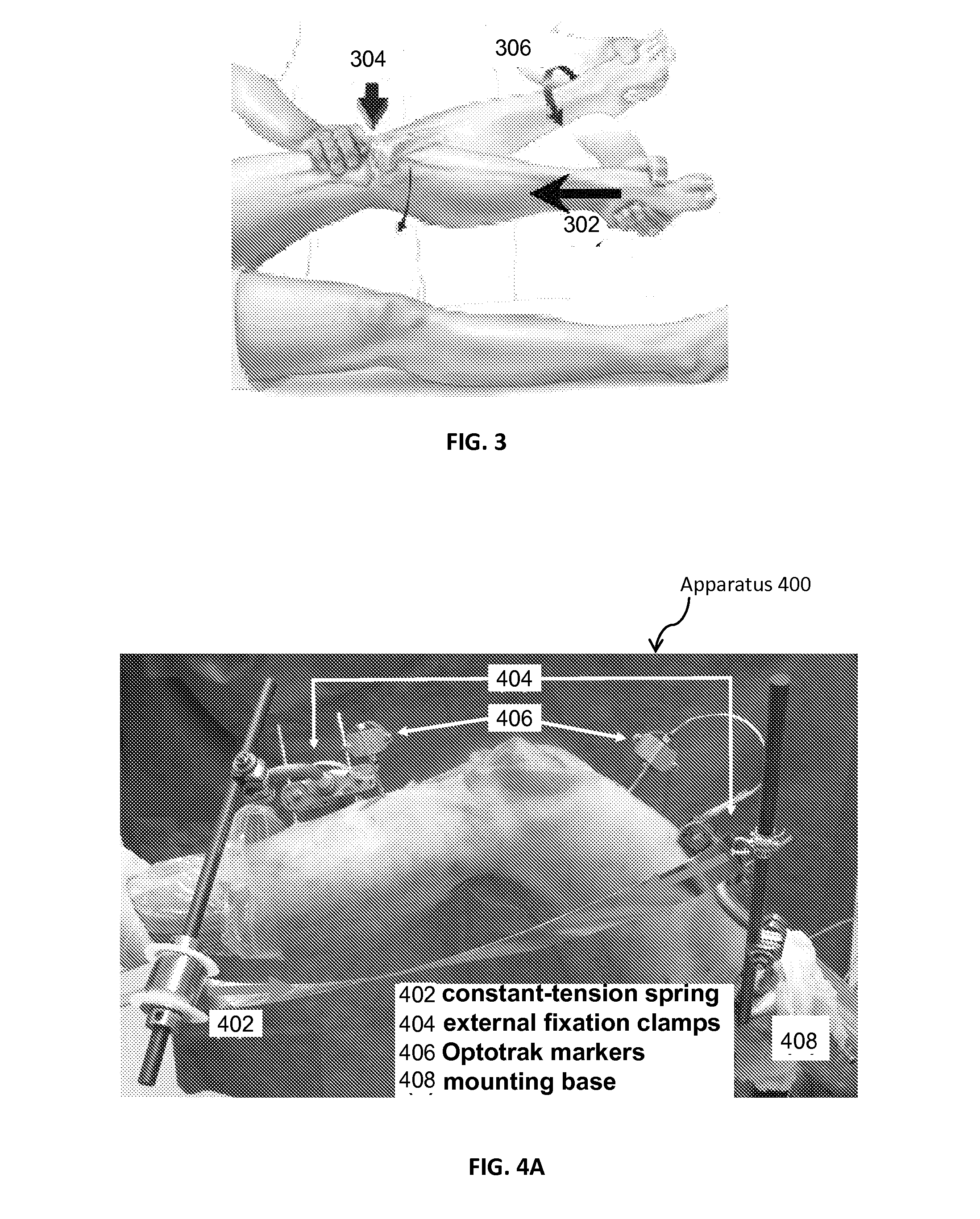
[0048]The mechanical pivot shift apparatus was used to reproduce a positive pivot shift in an ACL-deficient cadaver knee. The apparatus applied a standardized combination of multiplanar forces and moments to the knee utilizing a constant-tension spring, as illustrated in FIG. 4 to induce a consistent tibial subluxation / reduction event during knee flexion. The mechanical pivot shift apparatus was used to compare the 3D rotational and translational kinematics of knee motion during manual and mechanized pivot shift tests. Each test type was performed 3 to 5 times on both intact and ACL-deficient cadaveric knees (3 knees).

[0049]FIG. 5 is a graphical illustration of typical pivot shift trajectories for the manual pivot shift test performed manually and for the mechanical pivot shift test performed with the mechanical pivot shift apparatus, according to one or mo...


PUM


Abstract

An unmet need of orthopaedic practitioners is a clinically-relevant measurement device and technique to objectively quantify joint (e.g., knee) stability, including rotational stability. An apparatus and method is disclosed for performing a mechanical joint movement test, such as a knee pivot shift test, through the application of standardized dynamic loads (e.g., using a constant-tension spring or other mechanism). When used for knee evaluation, this test reliably induces the characteristic “pivot” tibial subluxation / reduction event in an ACL-deficient knee, allowing for more sensitive detection of deficiencies in rotational knee stability, quantification of the relative importance of knee stabilizers, and comparison of the performance of contemporary ACL reconstruction techniques. The test allows for better understanding joint biomechanics and for defining unique kinematic and kinetic signatures for common joint injuries, such as knee injuries, that will be valuable for diagnostic purposes.

Description

CROSS-REFERENCE TO RELATED APPLICATION[0001]This application claims the benefit of U.S. Provisional Application No. 61 / 521,627, filed Aug. 9, 2011, which is hereby incorporated by reference in its entirety.BACKGROUND OF THE INVENTION[0002]1. Field of the Invention[0003]The invention relates generally to evaluation of joints, and more specifically to mechanical pivot shift measurement to evaluate joints, such as instability in the knee.[0004]2. Description of the Related Art[0005]The anterior cruciate ligament (ACL) is an intra-articular ligament connecting the lateral femoral condyle to the proximal tibial plateau. The ACL is composed of two distinct functional bundles, the anteromedial (AM) bundle and the posterolateral (PL) bundle. These serve as a primary knee stabilizer and function in concert to limit tibial motion in a manner dependent on the angle of knee flexion. ACL injury is a common occurrence in many sports, with up to 135,000 ACL injuries leading to over 95,000 reconstr...

Claims


Application Information

Patent Timeline
IPC IPC(8): A61B5/11
CPCA61B5/11A61B5/1127A61B5/4585A61B5/4884
Inventor SENA, MARKFEELEY, BRIANCOUGHLIN, DEZBALOTZ, JEFF
Owner RGT UNIV OF CALIFORNIA
Learn More