
Retractable light-emitting structure

a light-emitting structure and retractable technology, applied in the direction of lighting and heating apparatus, semiconductor devices for light sources, lighting support devices, etc., can solve the problems of large risk, huge risk, effort, money and time invested in outdoor, decorative lights

Inactive Publication Date: 2013-02-14
WONG TSUI YUN
View PDF6 Cites 8 Cited by
  • Summary
  • Abstract
  • Description
  • Claims
  • Application Information

AI Technical Summary

Benefits of technology

The invention is about a light-emitting structure that has a retractable cover that can be customized for different holidays or user needs. It is designed to be permanent, but doesn't require constant installation and breakdown. The cover is easy to use and requires a simple installation process. The structure also has a washer between the moving and fixed housing to smoothly retract the mobile housing without noise.

Problems solved by technology

Traditional, decorative lights are installed for holidays and occasions such as Christmas, the Fourth of July, Halloween, etc. . . . The repetitive cycle of buying, unloading, installing, breaking down, packaging, and storing these festive lights can be an exhaustive process on any family.
Furthermore, there is a constant exposure to risk of injury each time these lights need to be installed.
In essence, there is a huge amount of risk, effort, money, and time invested into the installation of outdoor, decorative lights.
The aforementioned problems with outdoor, decorative light installations have plagued households for a long time.

Method used


Image

  • Retractable light-emitting structure
  • Retractable light-emitting structure
  • Retractable light-emitting structure

Examples


Embodiment Construction

[0029]The following preferred embodiments and figures will be described in detail so as to achieve aforesaid objects.

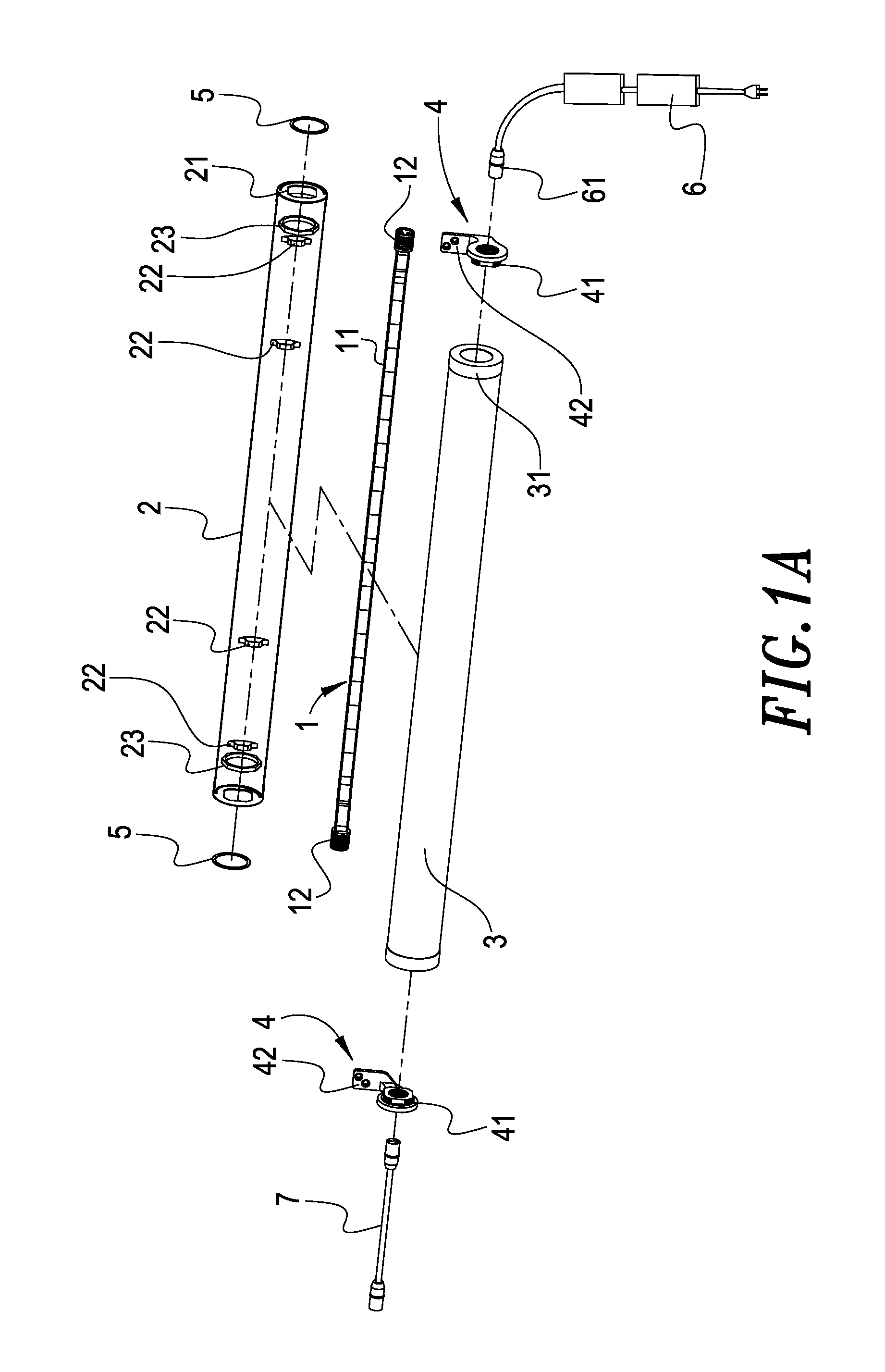
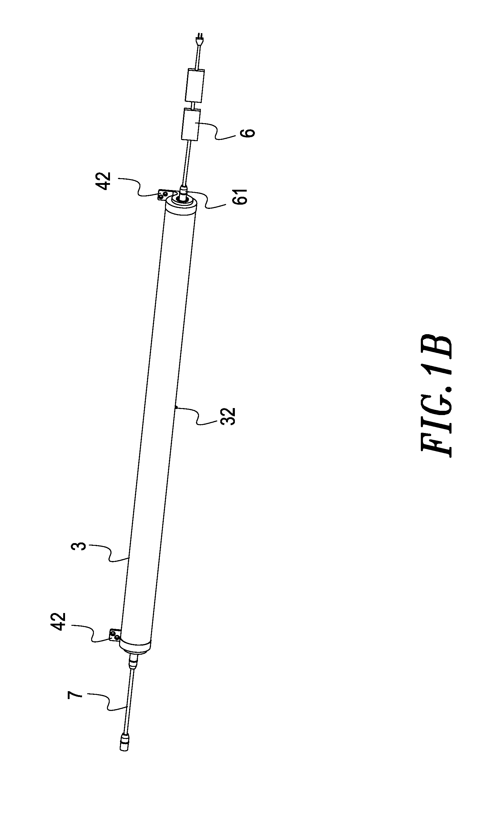
[0030]With references to FIG. 1A and FIG. 1B, which illustrate a 3-D exploded sketch of the retractable light-emitting structure of the present invention and a 3-D assembly sketch of the retractable light-emitting structure of the present invention. As shown in figures, the retractable light-emitting structure includes a LED strip light (light string structure) 1 having a plurality of LED bulbs 11, a fixed housing 2, each end of which has one fixed housing opening 21, and a mobile housing 3, each end of which has one mobile housing opening 31, wherein a plurality of brackets 22 and two connecting nuts 23 are disposed in the fixed housing 2, the brackets 22 are fixed in the internal of the fixed housing 2 through the LED strip light 1, the mobile housing 3 has a hook latch 32, therefore a user is able to hook the hook latch 32 through a rod member in order to lift or c...


PUM


Abstract

The retractable, light-emitting structure comprises of a string structure that has several light-emitting components: a fixed housing with openings at each end and a mobile housing with openings at each end. The ends of each housing are matched up to create a retractable lid that displays the emitting light inside the fixed housing. The mobile housing would inwardly retract along the fixed housing to make the retractable cover. These structures are ideally installed on the eaves or edges of a housing complex and are controlled by a remote control device that allows for color customization and the ability to control the mobile housing in accordance to different holidays, festivals, and user preference.

Description

BACKGROUND OF THE INVENTION[0001]1. Field of the Invention[0002]The present invention, generally, relates to a light-emitting structure that is disposed on walls, beneath draining tubes or under eaves. Functions include user customization of the device's opening and closing feature pending on varying occasions and situations.[0003]2. Description of the Prior Art[0004]Traditional, decorative lights are installed for holidays and occasions such as Christmas, the Fourth of July, Halloween, etc. . . . The repetitive cycle of buying, unloading, installing, breaking down, packaging, and storing these festive lights can be an exhaustive process on any family. Furthermore, there is a constant exposure to risk of injury each time these lights need to be installed. In essence, there is a huge amount of risk, effort, money, and time invested into the installation of outdoor, decorative lights.[0005]The aforementioned problems with outdoor, decorative light installations have plagued households...

Claims


Application Information

Patent Timeline
IPC IPC(8): F21S4/00
CPCF21V33/006F21S4/003F21Y2101/02F21W2121/004F21V21/005F21S4/20F21Y2115/10
Inventor WONG, TSUI-YUN
Owner WONG TSUI YUN
Learn More