
Electronic apparatus

Active Publication Date: 2013-02-07
SONY COMPUTER ENTERTAINMENT INC
View PDF5 Cites 8 Cited by
  • Summary
  • Abstract
  • Description
  • Claims
  • Application Information

AI Technical Summary

Benefits of technology

The patent describes a way to make sure that electronic components on a circuit board are positioned correctly and don't interfere with each other. This makes it easier to design and test the components, which can save time and money.

Problems solved by technology

Accordingly, a degree of freedom of the positions of the connectors is low, and the positions depending on the position of the circuit board are not always desirable.
Further, in electronic apparatuses including a cable arranged on the inner side thereof is used, interference between the cable and electronic components mounted on the circuit board tends to be a problem.

Method used


Image

  • Electronic apparatus
  • Electronic apparatus
  • Electronic apparatus

Examples


Embodiment Construction

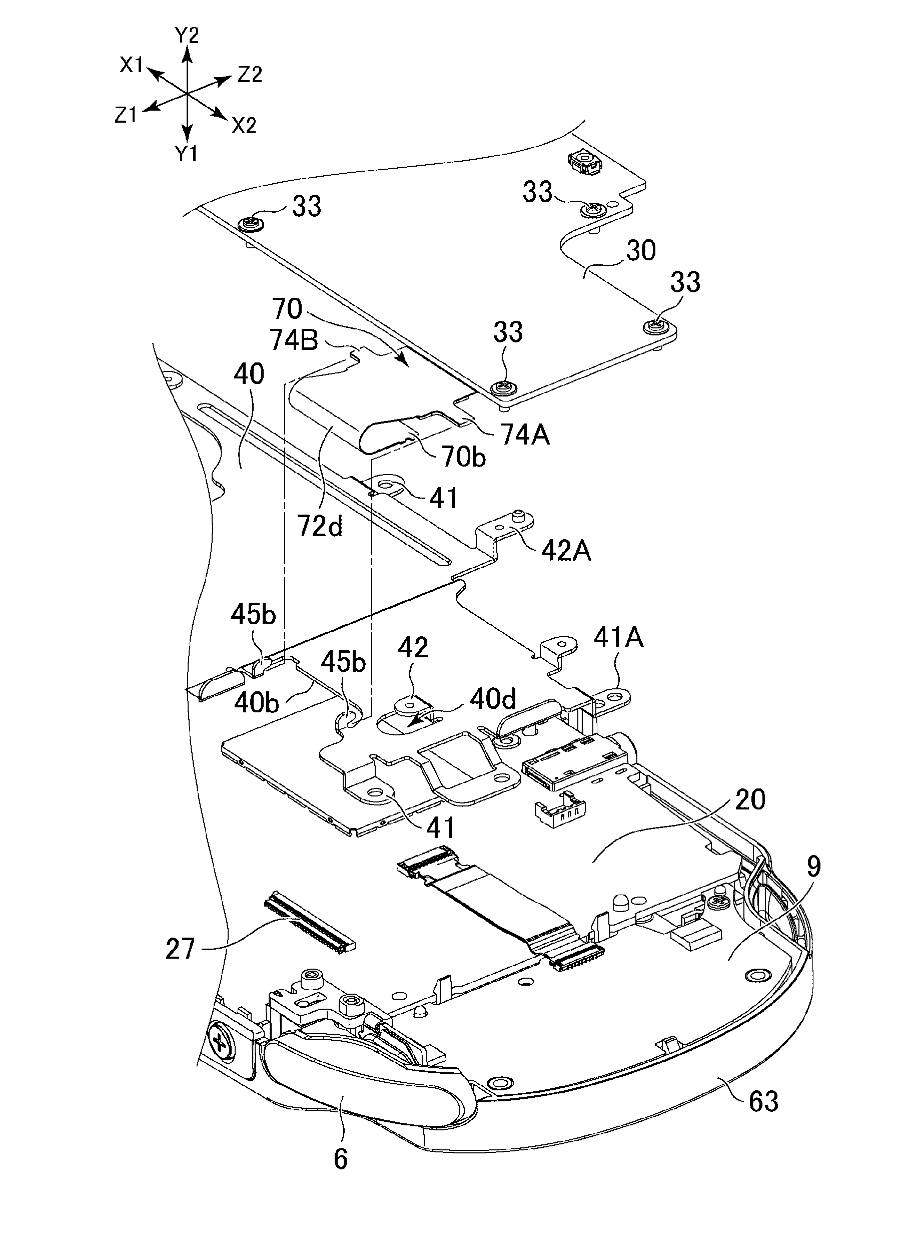
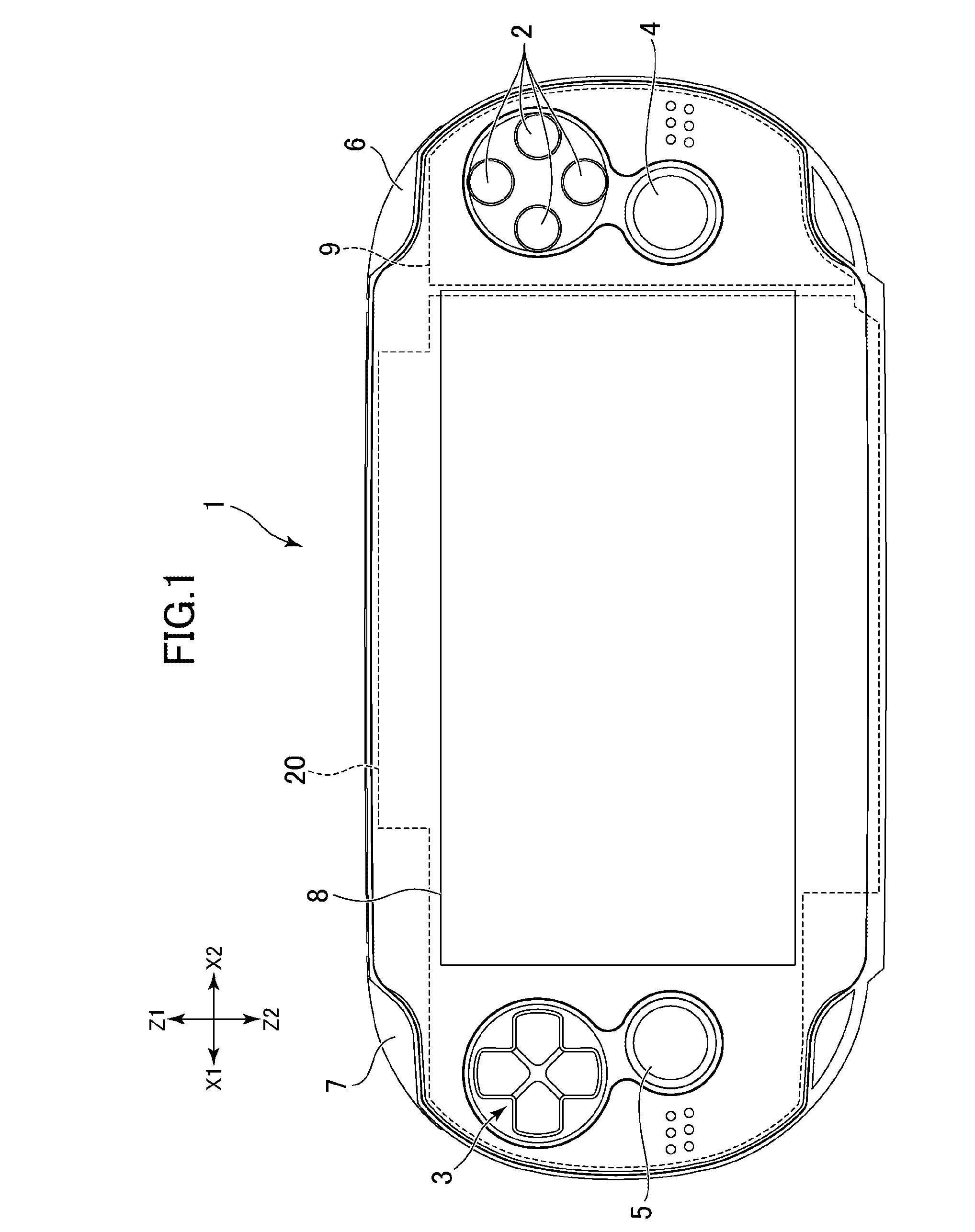
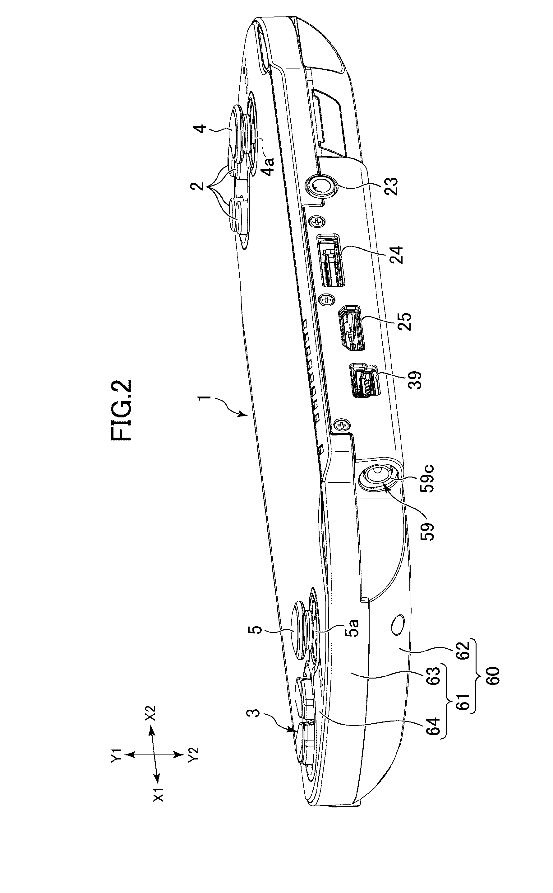
[0023]An embodiment of the present invention will be explained below with reference to the drawings. FIG. 1 is a front view of an electronic apparatus 1 according to the embodiment. FIG. 2 is a perspective view of the electronic apparatus 1 showing the lower surface thereof. FIG. 3 is an exploded perspective view of the electronic apparatus 1. FIG. 4 is a rear view of a circuit board 20 and an intermediate frame 40 shown in FIG. 3. FIG. 5 is a sectional view of the electronic apparatus 1 taken along line V-V shown in FIG. 4. FIG. 6 is a front view of a circuit board 30.

[0024]In the following explanation, X1 and X2 shown in FIG. 1 respectively indicate the left direction and the right direction and Z1 and Z2 shown in FIG. 1 respectively indicate the upward direction and the downward direction. Y1 and Y2 shown in FIG. 2 respectively indicate the front direction and the rear direction.

[0025]The electronic apparatus 1 is a portable electronic apparatus functioning as, for example, a gam...


PUM


Abstract

An electronic apparatus 1 includes a holder 50 arranged along the rear surface of a main board 20 and the front surface of a sub-board 30. The holder 50 includes a connector holder portion 51 that holds a connector 59 in a position offset in the thickness direction of the main board 20 and the sub-board 30 from a position on the rear surface of the main board 20 and a position on the front surface of the sub-board 30. The holder 50 includes a cable holder portion 52 that holds a cable 58. Consequently, it is possible to optimize the position of an electronic component such as a connector and prevent interference between a cable connected to the electronic component and other electronic components on a circuit board.

Description

CROSS-REFERENCE TO RELATED APPLICATION[0001]The present application claims priority from Japanese application JP2011-171287 filed on Aug. 4, 2011, the content of which is hereby incorporated by reference into this application.BACKGROUND OF THE INVENTION[0002]1. Field of the Invention[0003]The present invention relates to a structure for supporting an electronic component provided to be exposable on the outer surface of an electronic apparatus.[0004]2. Description of the Related Art[0005]United States Patent Application Publication No. 2007 / 0202956 discloses an electronic apparatus including a display screen on the front surface thereof. In the electronic apparatus, connectors for connecting the electronic apparatus to peripheral apparatuses are provided on the bottom surface and the side surfaces of a housing of the electronic apparatus. In some electronic apparatus of this type, connectors into which portable storage media can be inserted are provided on the bottom surface and the ...

Claims


Application Information

Patent Timeline
IPC IPC(8): H05K7/02H05K5/02H05K7/00H05K7/12
CPCH05K7/02A63F13/08A63F13/92
Inventor FURUBO, TAKAYUKIBEPPU, HIROKUNI
Owner SONY COMPUTER ENTERTAINMENT INC
Learn More