
Mammography-Apparatus

a technology of mammography and apparatus, applied in the field of mammography apparatus, can solve problems such as uneven pressure distribution

Active Publication Date: 2013-01-31
DALSA
View PDF2 Cites 15 Cited by
  • Summary
  • Abstract
  • Description
  • Claims
  • Application Information

AI Technical Summary

Benefits of technology

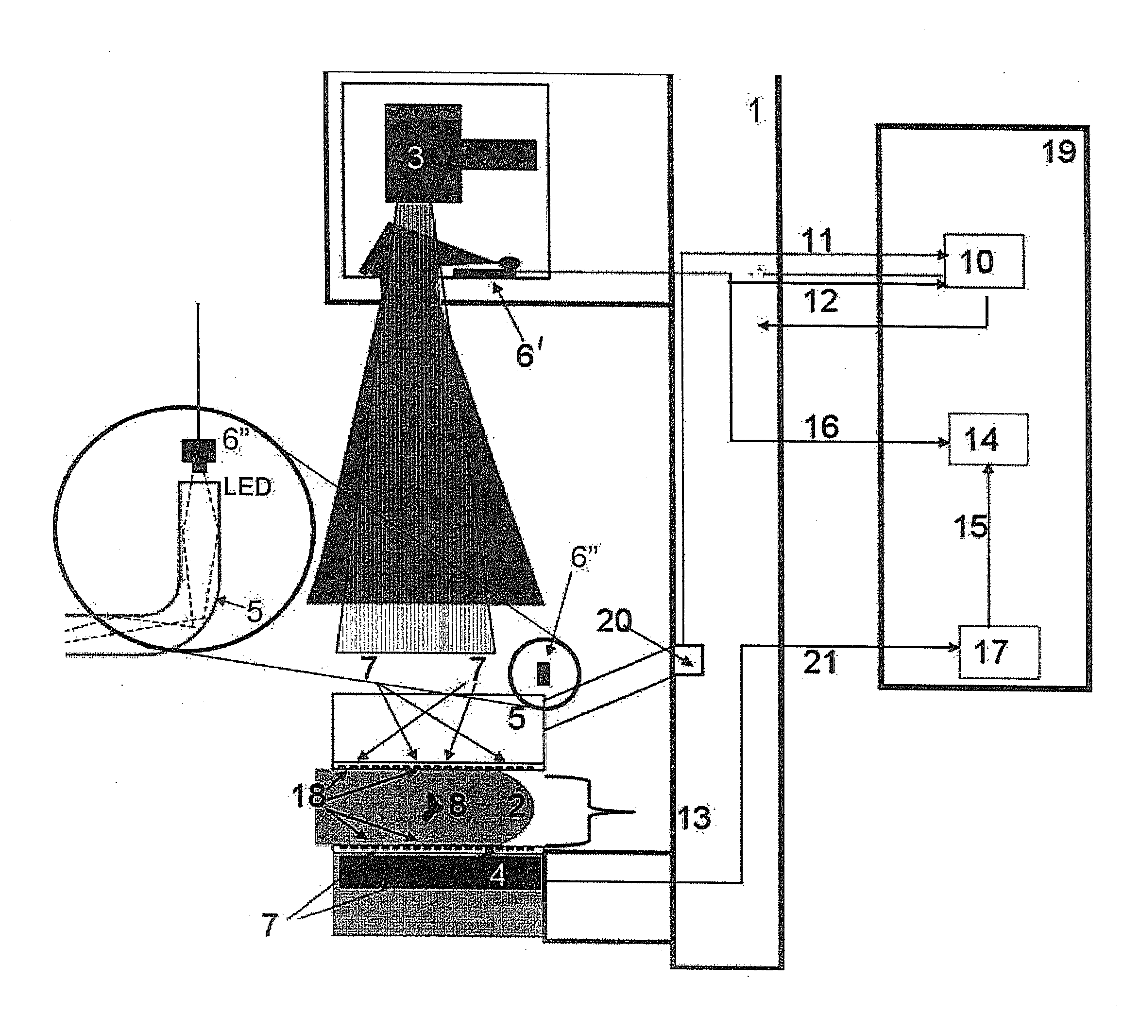
The invention aims to improve breast imaging by taking into account relevant parameters and avoiding unnecessary pressurization of the breast. It also aims to enhance the detection of malignant cells in breast tissue.

Problems solved by technology

One of the disadvantages of the known mammography-apparatus is that in order to improve the quality of x-ray imaging it is suggested to apply an uneven distribution of pressures to the breast.

Method used


Image

  • Mammography-Apparatus
  • Mammography-Apparatus

Examples


Embodiment Construction

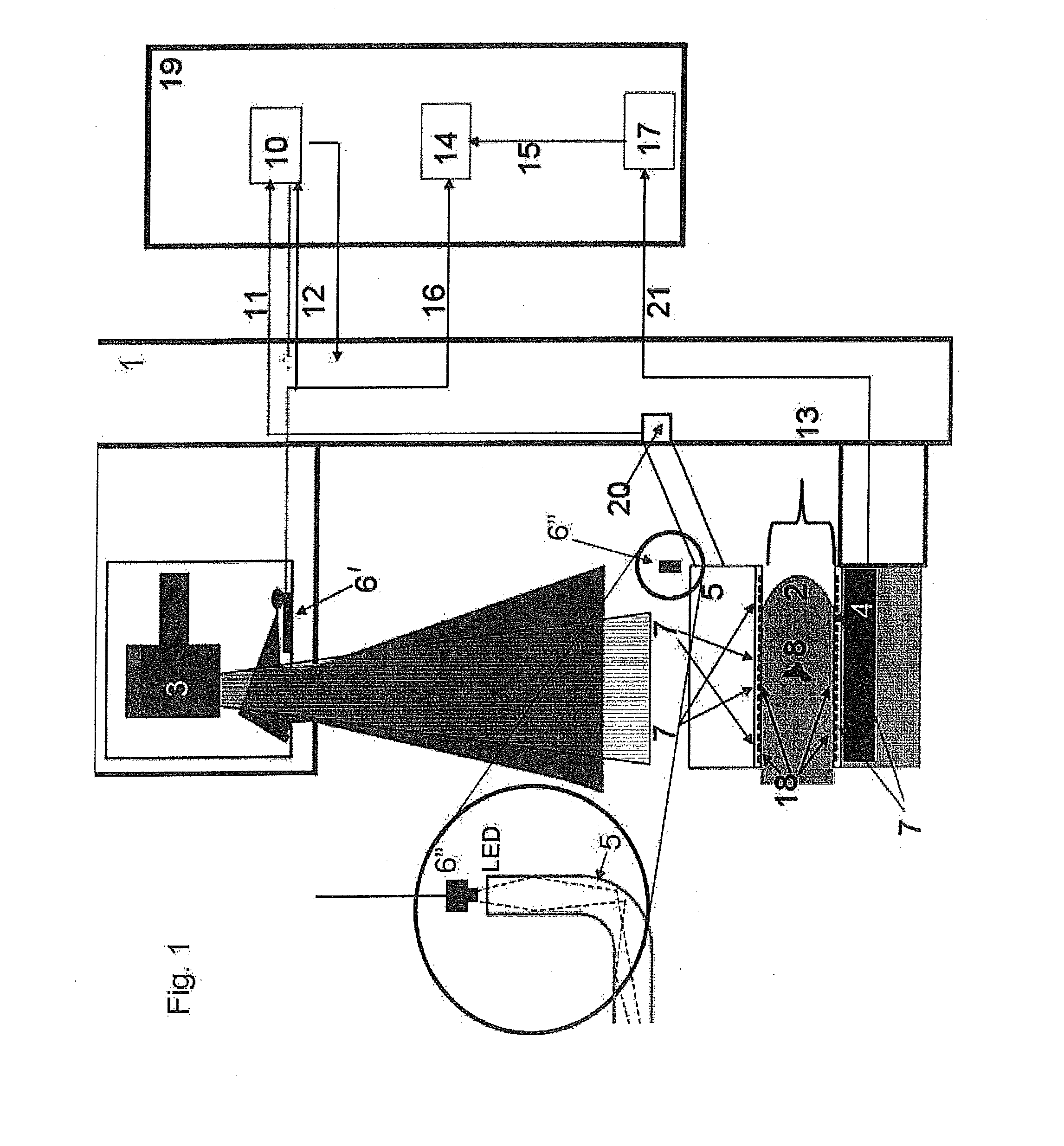
[0018]In a first aspect of the invention the mammography-apparatus has a contact area measuring unit for measuring the contact area between the breast and the paddle. In the mammography apparatus of the invention the paddle is preferably made unitary, that means in one piece, at least without the series of adjacent paddle elements that are individually movable and controllable as in the prior art according to U.S. Pat. No. 7,656,993.

[0019]The contact area measuring unit can be used in a dual fashion. In an embodiment in which the at least one sensor is used to measure the force that is applied to the breast, this force together with the contact area provides the average pressure that is applied to the breast. This average pressure can then be controlled at a pre-established level so as to avoid un-necessary and avoidable pain during imaging.

[0020]Further, the measured contact area between the breast and the paddle resulting from the breast-compression can be used together with the p...


PUM


Abstract

Mammography-apparatus for detecting malignant cells in a breast comprising an x-ray source and an x-ray detector that cooperates with the x-ray source for providing an x-ray image of said breast, and further comprising a paddle for flattening the breast by pressing it against said x-ray detector, wherein at least one sensor is applied for measuring a parameter that is used for determining the pressure at which the paddle compresses the breast, and wherein a control system is provided which controls the actuation of the paddle depending on the pressure that is applied to the breast, wherein there is a contact area measuring unit for measuring the contact area between the breast and the paddle.

Description

CROSS-REFERENCE TO RELATED APPLICATIONS[0001]This application is a continuation application of International Patent Application Serial No. PCT / NL2011 / 050095, entitled “Mammography-Apparatus”, to Academisch Medisch Centrum van de Universiteit van Amsterdam, filed on Feb. 10, 2011, which is a continuation of Netherlands Patent Application Serial No. 2004270, entitled “Mammography-Apparatus”, filed on Feb. 19, 2010; Netherlands Patent Application Serial No. 2005159, entitled “Mammography-Apparatus”, filed on Jul. 26, 2010; and Netherlands Patent Application Serial No. 2005509, entitled “Mammography-Apparatus”, filed on Oct. 13, 2010, and the specifications and claims thereof are incorporated herein by reference.STATEMENT REGARDING FEDERALLY SPONSORED RESEARCH OR DEVELOPMENT[0002]Not Applicable.INCORPORATION BY REFERENCE OF MATERIAL SUBMITTED ON A COMPACT DISC[0003]Not Applicable.COPYRIGHTED MATERIAL[0004]Not Applicable.BACKGROUND OF THE INVENTION[0005]1. Field of the Invention (Technic...

Claims


Application Information

Patent Timeline
IPC IPC(8): A61B6/04
CPCA61B6/0414A61B6/507A61B6/502
Inventor DEN HEETEN, GERARD JOHANGRIMBERGEN, CORNELIS ANTONIUS
Owner DALSA
Learn More