
Pad mechanism capable of adjusting height thereof and electronic device therewith

a technology of adjusting mechanism and pad body, which is applied in the direction of portable electronic device details, instruments, electric apparatus casings/cabinets/drawers, etc., can solve the problems of inconvenience for users to carry, inability to adjust the height of inability to tilt the portable electronic device, etc., to solve the drawback of assembly tolerances, improve the drawback of the conventional pad mechanism, and facilitate assembly and maintenan

Active Publication Date: 2013-01-10
WISTRON CORP
View PDF13 Cites 3 Cited by
  • Summary
  • Abstract
  • Description
  • Claims
  • Application Information

AI Technical Summary

Benefits of technology

The pad mechanism in this patent allows for easy adjustment of its height, which solves issues with traditional pads that cannot adjust their height. This mechanism improves the assembly and maintenance of electronic devices, provides stability on uneven surfaces, and allows users to adjust the height for better comfort. It also helps to improve heat-dissipating efficiency and reduce loading on the user's shoulders and neck while typing. Overall, this pad mechanism is an improvement over conventional pads and enhances the user experience of electronic devices.

Problems solved by technology

The drawback of the above-mentioned manner is that a height thereof is not adjustable.
Assembly tolerances when assembling the pad component and the portable electronic device or wearing after the pad component has been used for a period will cause the portable electronic device to tilt when it is placed on the supporting surface.
However, there are lots of mechanisms, such as a screw adjusting mechanism, a magnetic mechanism, a gear adjusting mechanism and so on, applied for the conventional supporting mechanism, such that the above-mentioned mechanisms with large volume occupy mechanical space and cause inconvenience for the user to carry.
Accordingly, it is hard for the above-mentioned mechanisms to be fit in the portable electronic devices with a trend to thinness and aesthetic.

Method used


Image

  • Pad mechanism capable of adjusting height thereof and electronic device therewith
  • Pad mechanism capable of adjusting height thereof and electronic device therewith
  • Pad mechanism capable of adjusting height thereof and electronic device therewith

Examples


Embodiment Construction

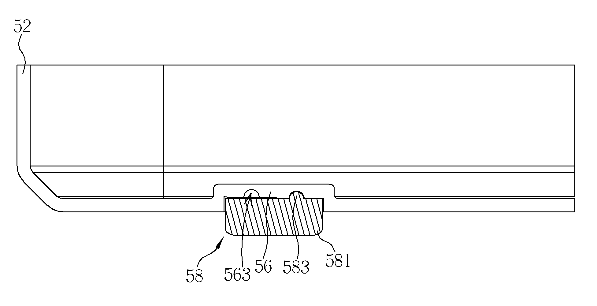
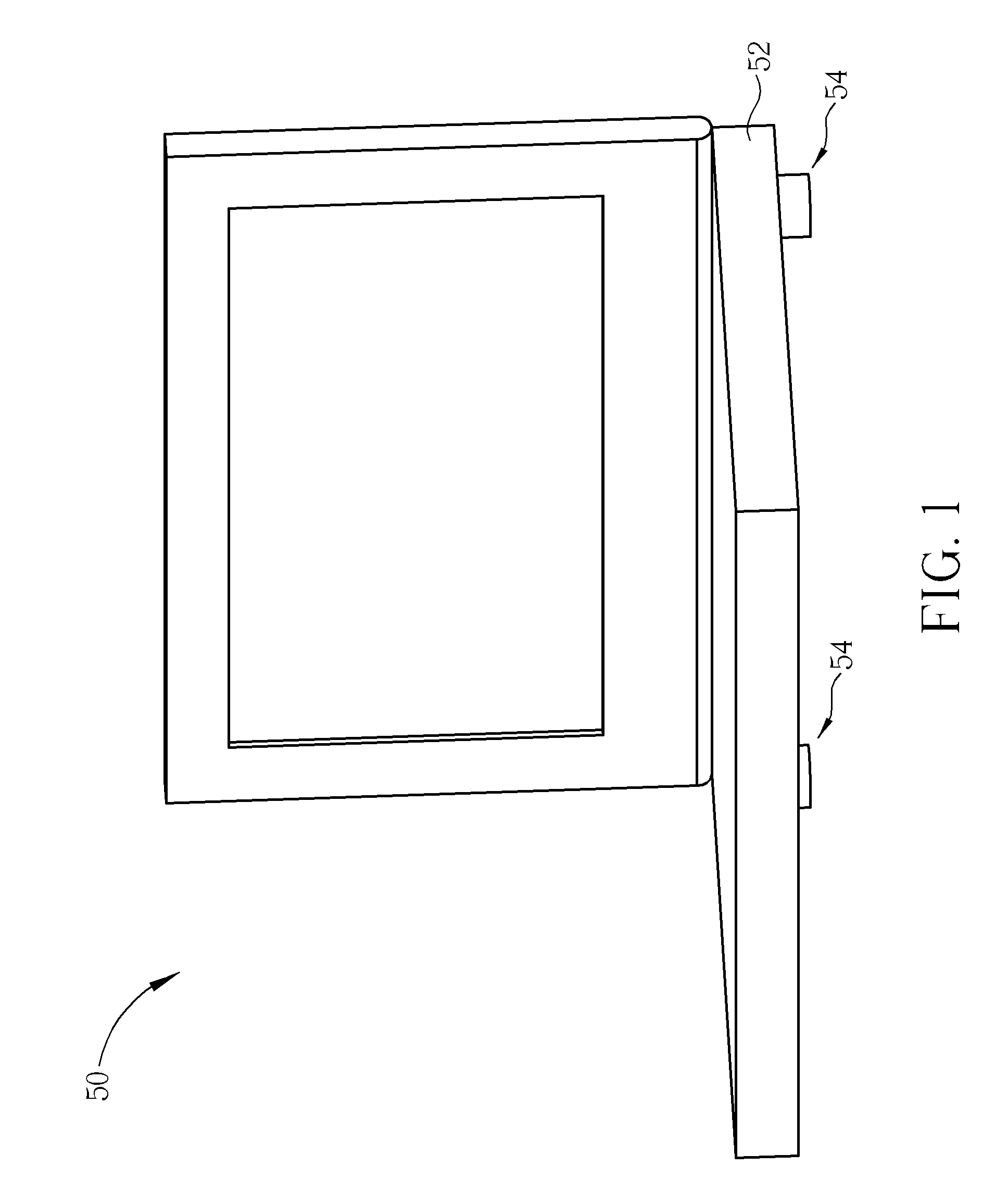
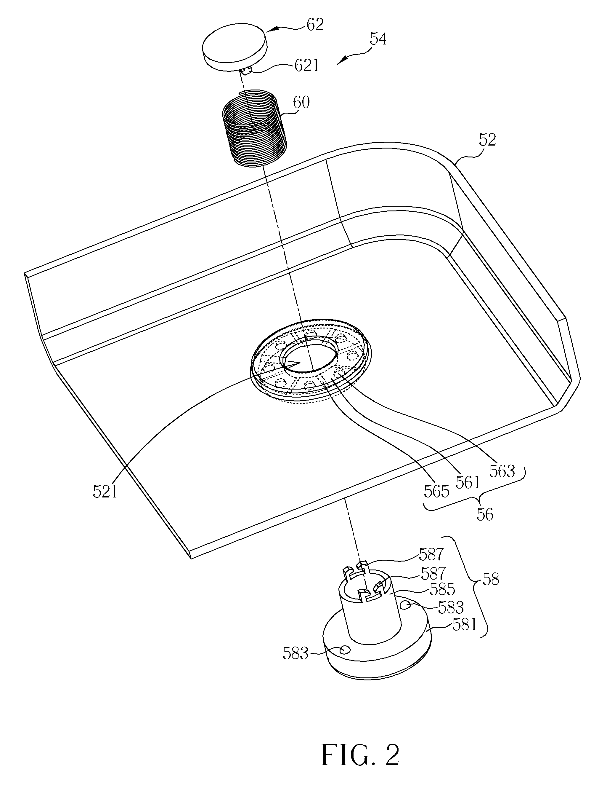
[0020]Please refer to FIG. 1. FIG. 1 is a diagram of an electronic device 50 according to an embodiment of the present invention. The electronic device 50 can be a portable electronic device, such as a notebook computer and so on. The electronic device 50 includes a casing 52 for covering internal components. The electronic device 50 further includes at least one pad mechanism 54 installed on the casing 52. The pad mechanism 54 is used for boosting the casing 52 of the electronic device 50 so as to not only prevent a bottom of the casing 52 from wearing, but also to enlarge a gap between the casing 52 and a supporting surface. Accordingly, the pad mechanism 54 can improve convection under the electronic device 50, such that heat-dissipating efficiency of the electronic device 50 is enhanced. Furthermore, the pad mechanism 54 can adjust a tilting angle of a keyboard of the electronic device 50, e.g. a portable computer device, and increase a height of a display to reduce loading of t...


PUM


Abstract

A pad mechanism includes a step fixing structure having a plurality of step platforms. A height difference is formed between the two step platforms. A first engaging portion is formed on each step platform. The pad mechanism further includes a pad component having a pad body, a sleeve and a constraining portion. A second engaging portion is formed on the pad body for selectively engaging with the corresponding first engaging portion so as to adjust a height of the pad body protruding from the step fixing structure. The pad mechanism further includes a resilient component sheathing with the sleeve for driving the sleeve, and a constraining component installed on a side of the resilient component and connected to the constraining portion so as to prevent the resilient component from separating from the sleeve.

Description

BACKGROUND OF THE INVENTION[0001]1. Field of the Invention[0002]The present invention relates to a pad mechanism and an electronic device therewith, and more particularly, to a pad mechanism capable of adjusting height thereof and an electronic device therewith.[0003]2. Description of the Prior Art[0004]Since portable electronic devices are getting popular recently, portable electronic devices increasingly change in practicality and functionality. Appearance of the portable electronic devices is progressed to thin and aesthetic to meet the customer's demands. In aspect of mechanical design of the portable electronic devices, a pad disposed on a bottom of the portable electronic device is for boosting the portable electronic device to prevent the bottom of the portable electronic device from wearing, and to enlarge a gap between the portable electronic device and a supporting surface so as to improve convection under the portable electronic device, such that heat-dissipating efficien...

Claims


Application Information

Patent Timeline
Patent Type & Authority Applications(United States)
IPC IPC(8): H05K7/00F16M11/22
CPCG06F1/166G06F1/1616
Inventor LEE, JIA-HUNGKUO, CHIEN-HENGLAI, YEN-CHANG
Owner WISTRON CORP
Learn More