
Switch

a technology of switch and spring spring, which is applied in the field of switches, can solve the problems of affecting the electrical conduction between the contacts and the increase in the size of the switch, and achieve the effect of reducing the range of movement of the leaf spring

Inactive Publication Date: 2013-01-10
OMRON AUTOMOTIVE ELECTRONICS CO LTD
View PDF7 Cites 4 Cited by
  • Summary
  • Abstract
  • Description
  • Claims
  • Application Information

AI Technical Summary

Benefits of technology

The present invention provides a switch with contacts in two leaf springs that can secure conduction even with dust adhering to the contacts. The switch reduces the range of movement of the leaf springs, which prevents damage to the switch during use.

Problems solved by technology

In such a switch, if dust or the like adheres to the contact, the dust becomes present between flat surfaces of the contacts at the time when the flat surfaces of the contacts slide on each other, and as a result electrical conduction between the contacts is impaired.
Moreover, an increase in the range of movement of the leaf spring directly leads to an increase in the size of the switch.

Method used


Image

  • Switch
  • Switch
  • Switch

Examples


Embodiment Construction

[0026]Hereafter, embodiments of the present invention will be described with reference to the accompanying drawings. Throughout the drawings, the same or corresponding components are denoted by the same reference letters. In embodiments of the invention, numerous specific details are set forth in order to provide a more thorough understanding of the invention. However, it will be apparent to one of ordinary skill in the art that the invention may be practiced without these specific details. In other instances, well-known features have not been described in detail to avoid obscuring the invention.

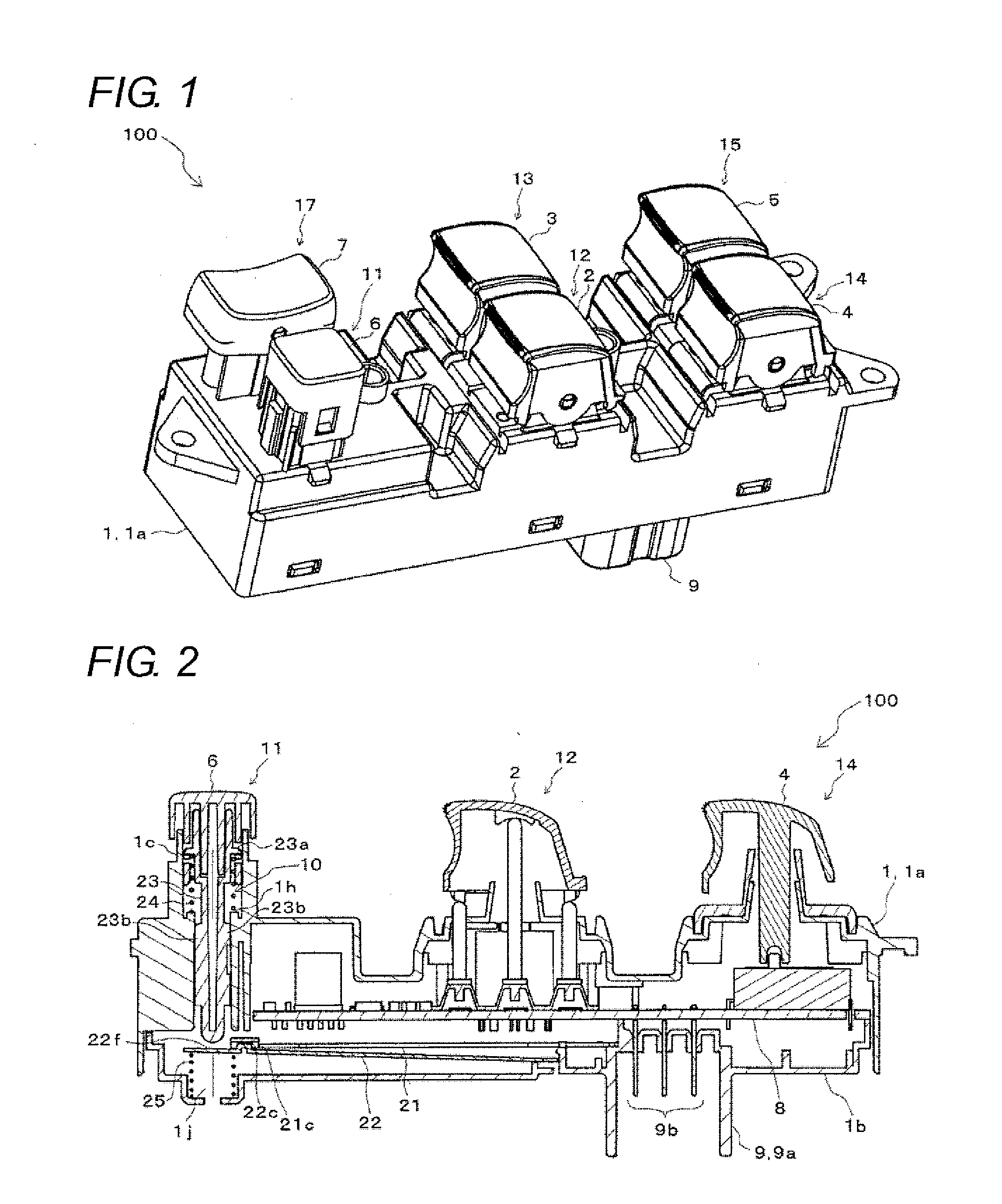
[0027]A switch unit 100 illustrated in FIG. 1 is a switch module for power window. The switch unit 100 is attached to an armrest installed on a door near the driver's seat in a vehicle.

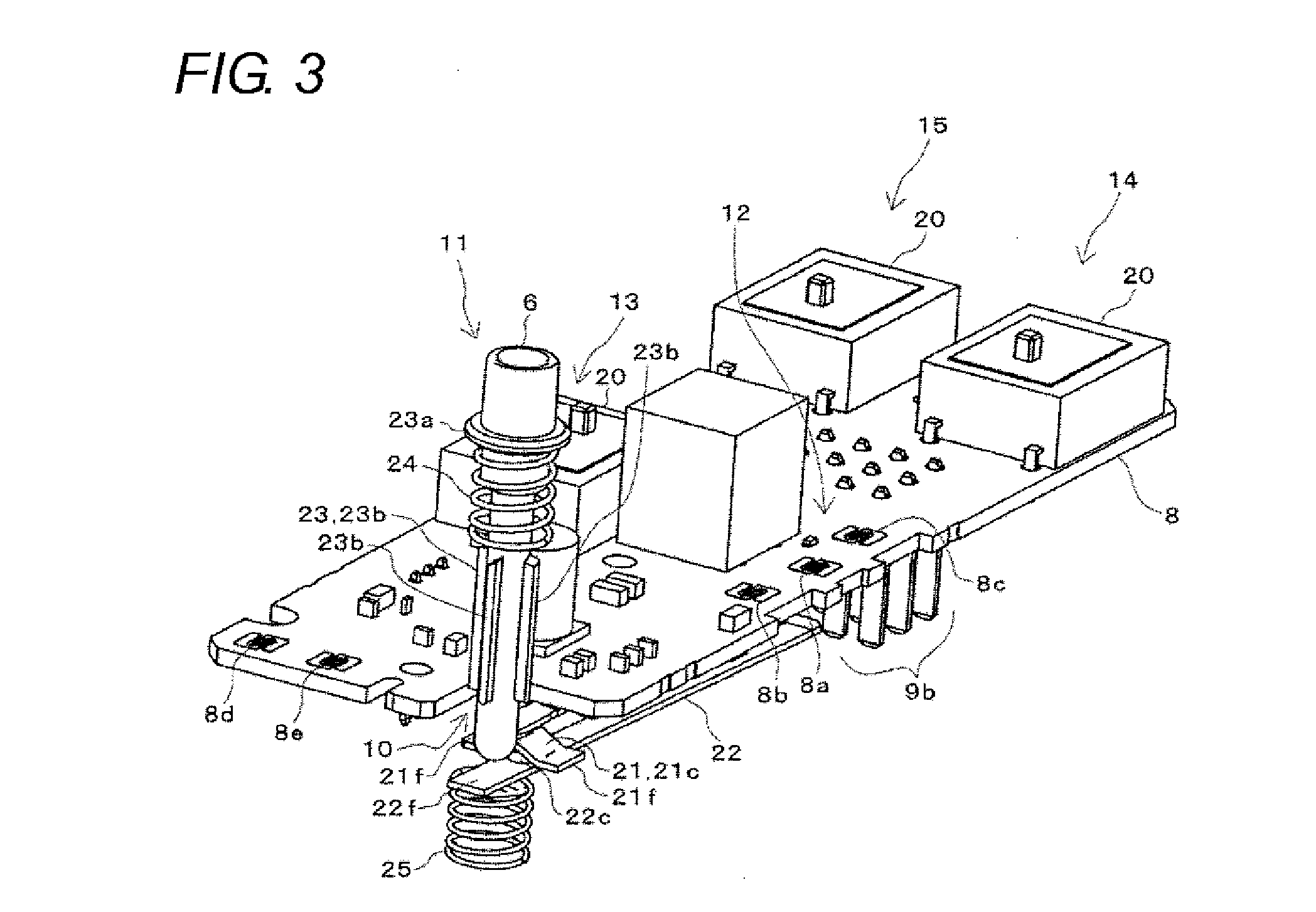
[0028]The switch 11 according to one embodiment of the present invention is provided in the switch unit 100. The switch 11 is a window lock switch to lock glass windows of respective seats in the vehicle so th...


PUM


Abstract

A switch has a first leaf spring having a first contact, the first contact being formed in a V shape and including two inclined surfaces, a second leaf spring having a second contact facing the first contact, the second contact being formed in a convex shape and including vertexes facing the inclined surfaces, respectively; and a pressing unit that presses the first leaf spring or the second leaf spring. When the pressing unit presses the first leaf spring or the second leaf spring, the inclined surface on a first side of the first contact and the vertex on a first side of the second contact come in contact with each other, and the vertex on the first side of the second contact slides on the inclined surface on the first side of the first contact.

Description

BACKGROUND OF THE INVENTION[0001]1. Technical Field[0002]The present invention relates to a switch with contacts provided in two leaf springs.[0003]2. Related Art[0004]As a switch with contacts provided in two leaf springs, for example, there is a known switch disclosed in Japanese Unexamined Patent Publication No. 2002-175735. In this switch, contacts (contact portions) to come in contact with each other are provided at free ends of two leaf springs (electric contacts). Each contact includes an inclined surface and a vertical surface. When a first leaf spring is pressed in a state in which the inclined surface of the first leaf spring and the inclined surface of a second leaf spring are in contact with each other, a contact of the first leaf spring is displaced in a pressing direction, and as a result the inclined surfaces of both the leaf springs come to slide. As a result, a contact of the second leaf spring is displaced in a direction which intersects the pressing direction, and...

Claims


Application Information

Patent Timeline
Patent Type & Authority Applications(United States)
IPC IPC(8): H01H1/26
CPCH01H1/18H01H2001/265H01H13/56
Inventor NOSE, TAKASHISAKAI, MANABUTANAKA, YASUHIDEGOTO, AKIRAYOSHIKAWA, HIDETOSHINISHIOKA, TAKUYANAKANO, SHIHO
Owner OMRON AUTOMOTIVE ELECTRONICS CO LTD
Learn More