
Cam Unit for a Constructed Camshaft

a cam unit and camshaft technology, applied in the direction of engine components, mechanical equipment, machines/engines, etc., can solve the problems of not being able to insert the camshaft transversely, assembling the built-up camshaft in a one-piece bearing block, and being generally extremely problematic, so as to simplify the assembly of the camshaft module

Active Publication Date: 2013-01-03
THYSSENKRUPP PRESTA TECCENTER AG
View PDF5 Cites 31 Cited by
  • Summary
  • Abstract
  • Description
  • Claims
  • Application Information

AI Technical Summary

Benefits of technology

The present invention provides a cam unit that is divided into individual components that can be easily manufactured and designed to meet different technical requirements. The modular design of the cam unit simplifies assembly of a camshaft module and the installation of the camshaft into the bearing receptacle of the module. Overall, the invention provides a more efficient and flexible approach to cam design and assembly.

Problems solved by technology

It is not possible to insert the camshaft transversely to the rotational axis thereof into a corresponding bearing receptacle in the case of such bearing receptacles.
Assembling built-up camshafts in a one-piece bearing block or in a one-piece ladder frame or in a closed bearing of a cylinder head cover (monolithic cylinder head cover) or the like is generally extremely problematic owing to the narrow constructional space and the assembly process that is complicated as a result.
In the former case, increased production and assembly outlay is generally unavoidable.
In the latter case, the increase in the bearing diameter results in increased friction in the valve train and a negative effect, associated therewith, with respect to the required constructional space.

Method used


Image

  • Cam Unit for a Constructed Camshaft
  • Cam Unit for a Constructed Camshaft
  • Cam Unit for a Constructed Camshaft

Examples


Embodiment Construction

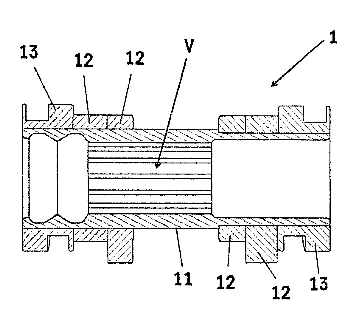
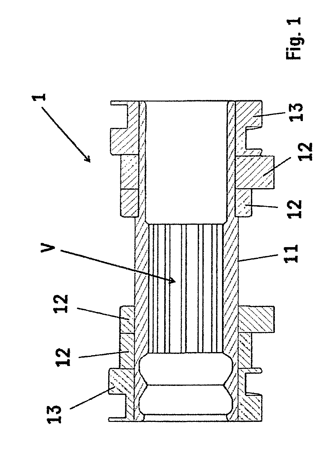
[0014]FIG. 1 shows a cam unit 1 having a main tubular sleeve body 11 that supports, on each of its two free ends (at the ends), a track element 13 and also on both sides two individual disk elements (hereinafter also referred to as cam elements 12) adjacent to each other towards the inner sides. The main sleeve body 11 and also the individual cam elements 12 and the track elements 13 on both sides are produced as individual separate components. The individual components are assembled together during different assembly steps to form a cam unit in accordance with the invention (which is also referred to as a so-called “switchable cam” with different cam tracks). In the completely assembled cam unit 1, the individual components, such as the main sleeve body 11, cam element 12 and track element 13, are connected together such that a rotationally-fixed and non-displaceable connection is formed between the main sleeve body 11 and the components 12, 13 to be attached thereto. The different...


PUM

PropertyMeasurementUnit
compositionsaaaaaaaaaa
outer diameteraaaaaaaaaa
inner diameteraaaaaaaaaa

Abstract

A cam unit for arranging on a camshaft main part of a camshaft in a rotationally fixed and axially movable manner. The cam unit includes a tubular sleeve main part and at least one cam element that lies on the sleeve main part in a rotationally fixed and non-movable manner. The sleeve main part and the at least one cam element are designed as individual parts that can be separately produced and subsequently assembled.

Description

BACKGROUND AND SUMMARY OF THE INVENTION[0001]Exemplary embodiments of the present invention relate to a (built-up) cam unit for the rotationally-fixed and axially displaceable arrangement on a main camshaft body of a camshaft (which is built-up or is to be built-up). Moreover, exemplary embodiments of the present invention encompass a camshaft having a main camshaft body and a cam unit disposed on the main camshaft body in a rotationally-fixed and axially displaceable manner, in accordance with the main claim. Furthermore, exemplary embodiments of the present invention encompass a camshaft module which supports, in an at least partially peripherally closed bearing device, a built-up camshaft having a drivable main camshaft body and at least one cam unit mounted on the main camshaft body in an axially displaceable and rotationally-fixed manner, in accordance with the main claim.[0002]German Patent Document DE 10 2004 011 586 A1 discloses a valve train for an internal combustion engin...

Claims


Application Information

Patent Timeline
Patent Type & Authority Applications(United States)
IPC IPC(8): F16H53/02
CPCF01L13/0036Y10T29/49293Y10T74/2101F01L2013/0052
Inventor WIESNER, PETERMUSTER, MANFREDBINDER, THOMASHEYWOOD, JONATHAN
Owner THYSSENKRUPP PRESTA TECCENTER AG
Learn More