
Multiple charge-coupled biometric sensor array

a biometric sensor and array technology, applied in the field of fingerprint scanning, can solve the problems of inability to provide accurate fingerprint information without time-consuming calibration, inability to accurately detect fingerprints, and inability to accurately identify fingerprints, etc., and achieve the effect of accurate fingerprint information and accurate fingerprint information

Active Publication Date: 2012-12-20
KIM MOON J
View PDF6 Cites 7 Cited by
  • Summary
  • Abstract
  • Description
  • Claims
  • Application Information

AI Technical Summary

Benefits of technology

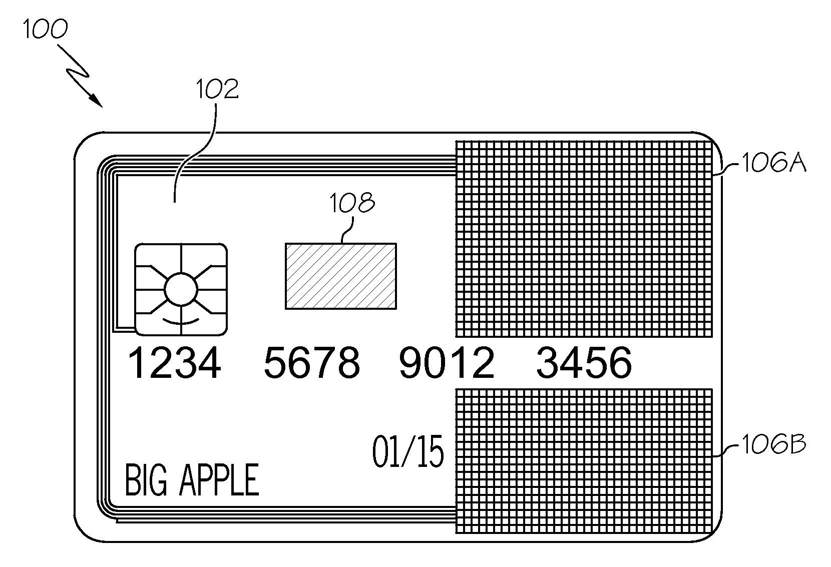
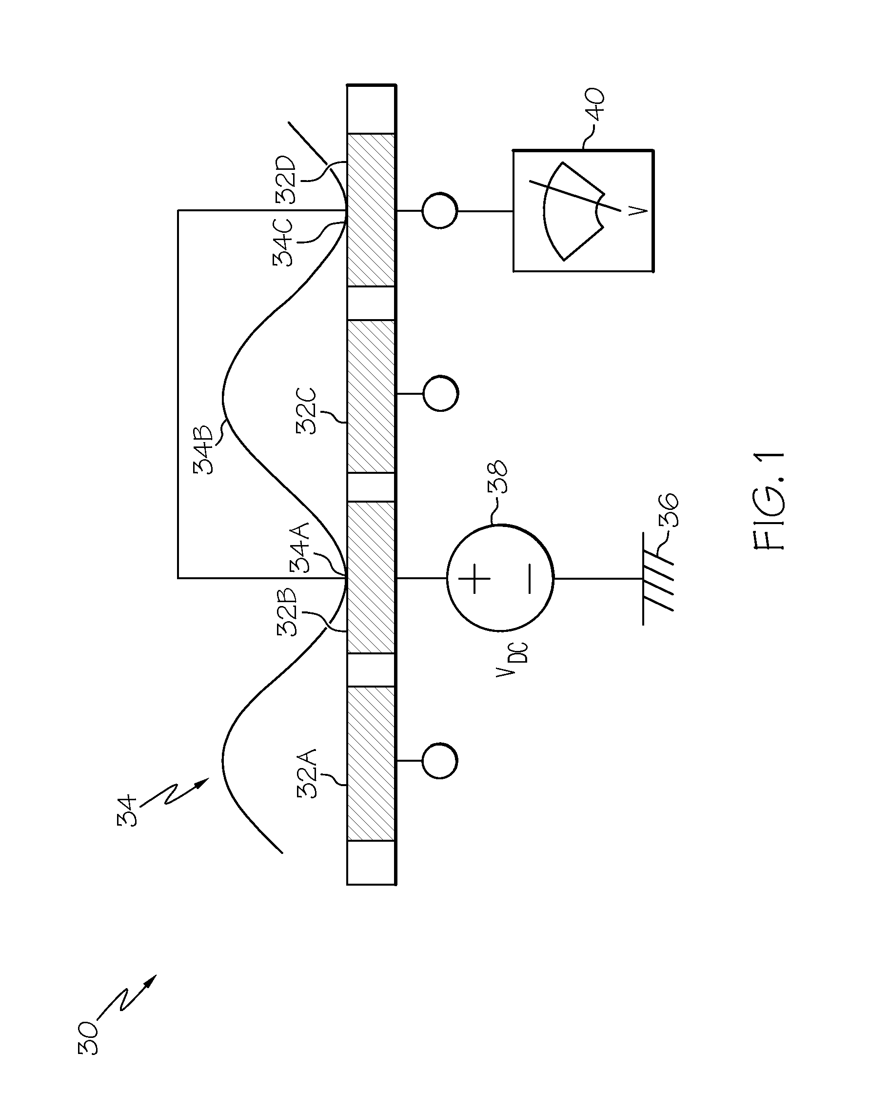
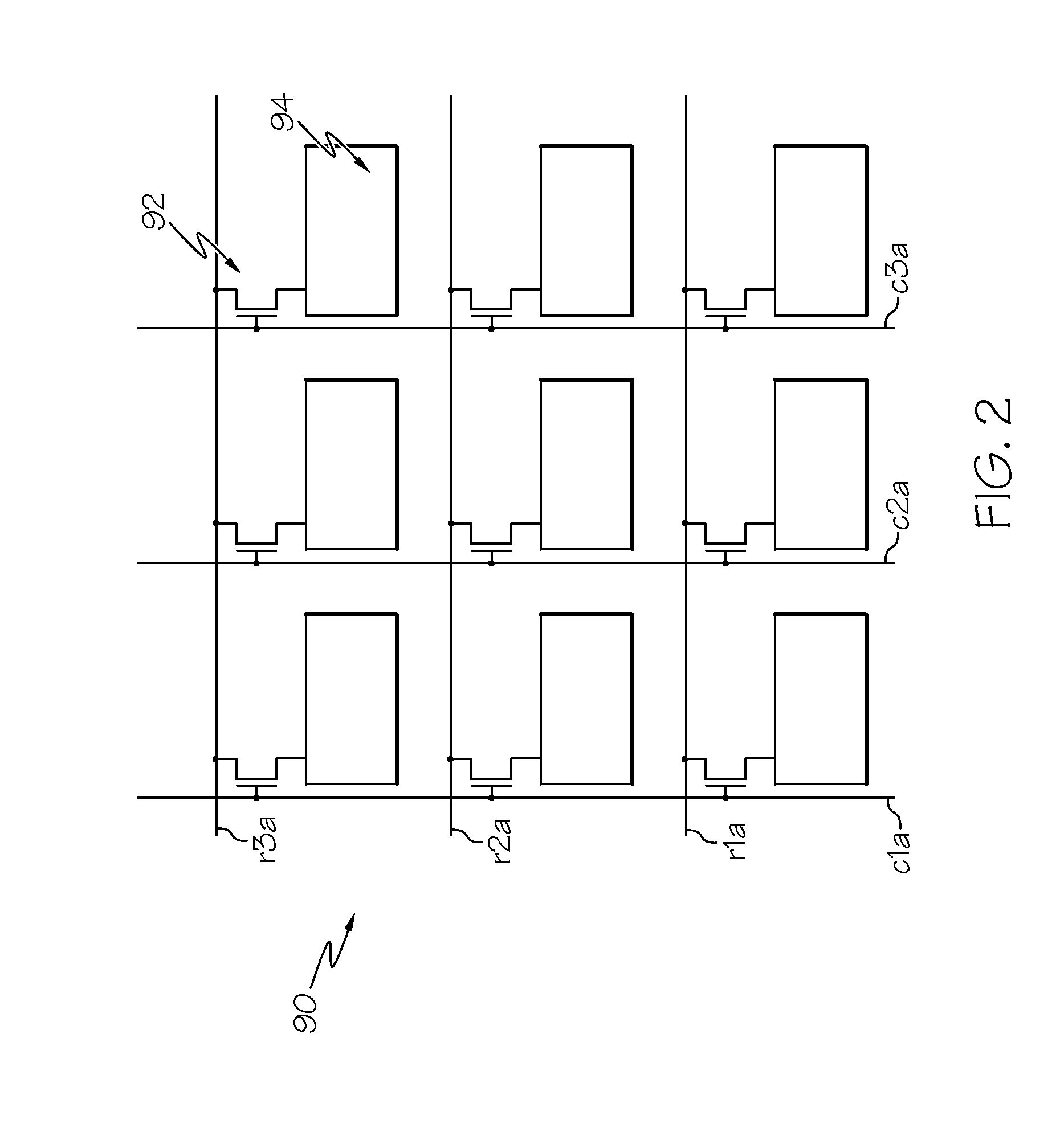
[0015]In general, the embodiments of the present invention relate to fingerprint scanning. Specifically, the present invention relates to a multi-sided fingerprint scanning device on a card (e.g., credit card, smart card, etc.), an associated energy-efficient method for attaining accurate fingerprint information using a multiple charge-coupled biometric sensor array. In a typical embodiment, a scanning device will be provided that includes a scanning area comprised of a set (e.g., at least one) of imaging pixel electrodes (e.g., arranged adjacent to one another in a grid-like or other fashion). As a user presses his/her finger against the scanning area, a portion of the finger will contact a plurality of electrodes. When this occurs, a voltage source of the dev

Problems solved by technology

Existing fingerprint imaging methods are energy inefficient and require careful calibration.
Heretofore, several unsuccessful attempts have been made to address these shortcomings.
None of these references, however, teach an energy efficient way to provide accurate fingerprint information without time-consuming calibration.

Method used


Image

  • Multiple charge-coupled biometric sensor array
  • Multiple charge-coupled biometric sensor array
  • Multiple charge-coupled biometric sensor array

Examples


Embodiment Construction

[0030]Illustrative embodiments will now be described more fully herein with reference to the accompanying drawings, in which exemplary embodiments are shown. This disclosure may, however, be embodied in many different forms and should not be construed as limited to the exemplary embodiments set forth herein. Rather, these exemplary embodiments are provided so that this disclosure will be thorough and complete and will fully convey the scope of this disclosure to those skilled in the art. In the description, details of well-known features and techniques may be omitted to avoid unnecessarily obscuring the presented embodiments.

[0031]The terminology used herein is for the purpose of describing particular embodiments only and is not intended to be limiting of this disclosure. As used herein, the singular forms “a”, “an”, and “the” are intended to include the plural forms as well, unless the context clearly indicates otherwise. Furthermore, the use of the terms “a”, “an”, etc., do not de...


PUM


Abstract

Embodiments of the present invention relate to fingerprint scanning. Specifically, the present invention relates to a multi-sided fingerprint scanning device on a card (e.g., credit card, smart card, etc.), an associated energy-efficient method for attaining accurate fingerprint information using a multiple charge-coupled biometric sensor array. In a typical embodiment, a scanning device will be provided that includes a scanning area comprised of a set (e.g., at least one) of imaging pixel electrodes (e.g., arranged adjacent to one another in a grid-like or other fashion). As a user presses his / her finger against the scanning area, a portion of the finger will contact a plurality of electrodes. When this occurs, a voltage source of the device will apply a first voltage to each of the plurality of electrodes. A meter of the device will take a first electrical measurement (e.g., resistance and / or charged skin voltage) of the plurality of electrodes. The voltage source of the device will apply a second voltage to the plurality of electrodes. The meter of the device will take a second electrical measurement (e.g., resistance and / or charged skin voltage) of the plurality of electrodes. The voltage level difference between the first electrical measurement and second electrical measurement is calculated. The voltage level difference provides accurate fingerprint information.

Description

CROSS-REFERENCE TO RELATED APPLICATIONS[0001]The present invention is related in some aspects to commonly owned, and co-pending application Ser. No. 13 / 096,179, entitled “ADAPTIVE FINGERPRINT SCANNING”, filed Apr. 28, 2011, and having attorney docket number IMSC-0008, the entire contents of which are herein incorporated by reference. The present invention is also related in some aspects to commonly owned, and co-pending application Ser. No. 13 / 106,928, entitled “MULTI-SIDED CARD HAVING A RESISTIVE FINGERPRINT IMAGING ARRAY”, filed May 13, 2011, and having attorney docket number IMSC-0012, the entire contents of which are herein incorporated by reference.FIELD OF THE INVENTION[0002]In general, the present invention relates to fingerprint scanning. Specifically, the present invention relates to a multi-sided fingerprint scanning device on a card (e.g., credit card, smart card, etc.), an associated energy-efficient method for attaining accurate fingerprint information using a multiple ...

Claims


Application Information

Patent Timeline
IPC IPC(8): G06K9/00
CPCG06K9/00G06K9/0002G07C9/00071G07C2009/00095G07C9/26G06V40/1306G07C9/25
Inventor KIM, MOON J.
Owner KIM MOON J
Learn More