
Azicon beam polarization devices

a technology of polarizing device and azicon beam, which is applied in the field of polarizing device, can solve the problems of limited beam null depth and incomplete destructive interference, and achieve the effect of reducing the cross-sectional area of the beam

Active Publication Date: 2012-12-20
US DEPT OF HEALTH & HUMAN SERVICES
View PDF2 Cites 14 Cited by
  • Summary
  • Abstract
  • Description
  • Claims
  • Application Information

AI Technical Summary

Benefits of technology

[0009]Methods comprise separating portions of an optical beam propagating along an axis and having first and second states of polarization at a surface of a first axicon by reflecting the beam portion in the first state of polarization and transmitting the beam portion in a second state of polarization. A second axicon is situated so that the reflected beam portion from the first ax...

Problems solved by technology

However, even if beam phase is precisely controlled, destructive interference may not be complete depending on the beam state of polarization.
If the optical beam is radially polarized, the beam will have axial components that do not interfere destructively, and the depth of the beam null will be limited.

Method used


Image

  • Azicon beam polarization devices
  • Azicon beam polarization devices
  • Azicon beam polarization devices

Examples


Embodiment Construction

[0017]As used in this application and in the claims, the singular forms “a,”“an,” and “the” include the plural forms unless the context clearly dictates otherwise. Additionally, the term “includes” means “comprises.” Further, the term “coupled” does not exclude the presence of intermediate elements between the coupled items.

[0018]The systems, apparatus, and methods described herein should not be construed as limiting in any way. Instead, the present disclosure is directed toward all novel and non-obvious features and aspects of the various disclosed embodiments, alone and in various combinations and sub-combinations with one another. The disclosed systems, methods, and apparatus are not limited to any specific aspect or feature or combinations thereof, nor do the disclosed systems, methods, and apparatus require that any one or more specific advantages be present or problems be solved. Any theories of operation are to facilitate explanation, but the disclosed systems, methods, and a...


PUM


Abstract

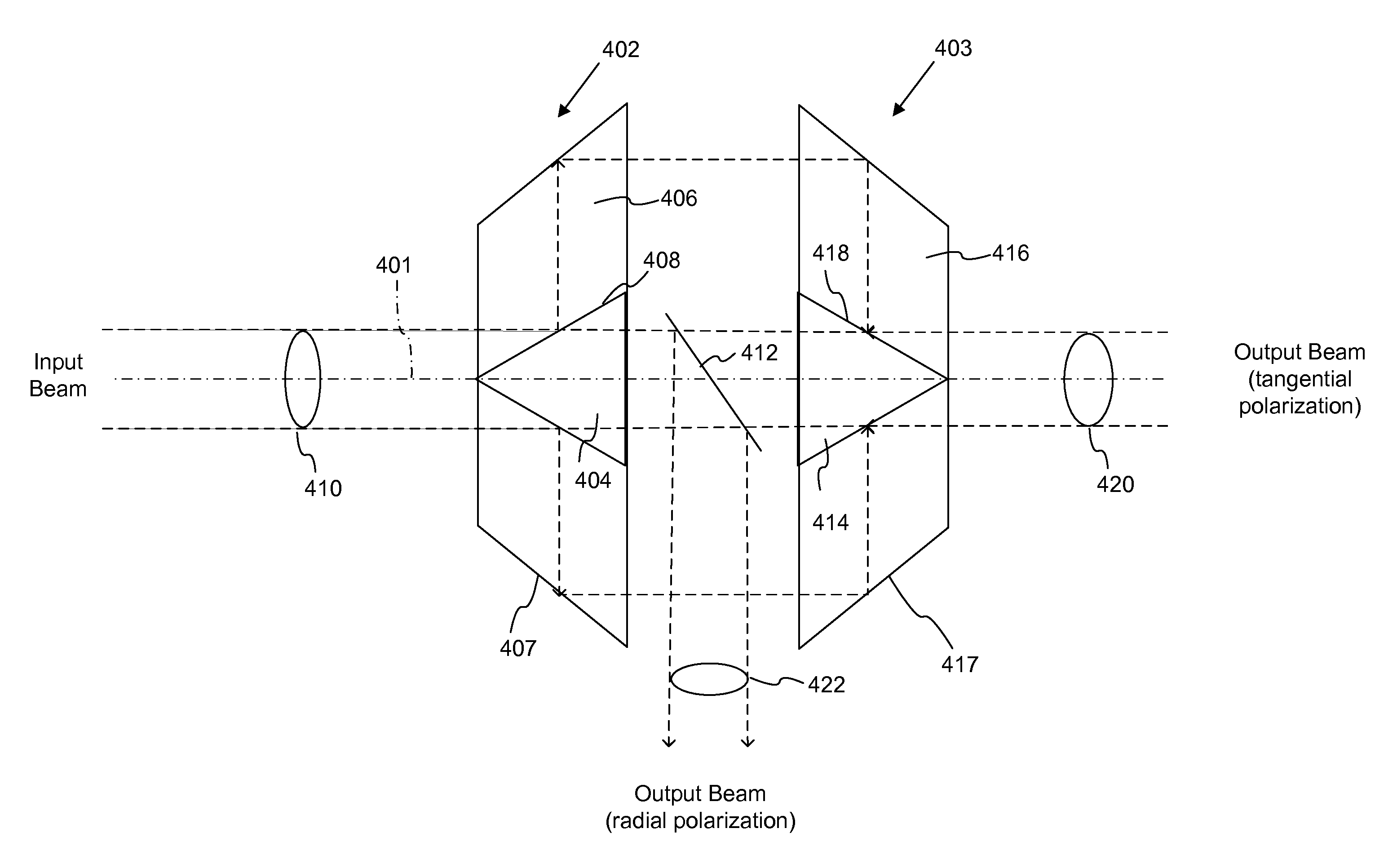
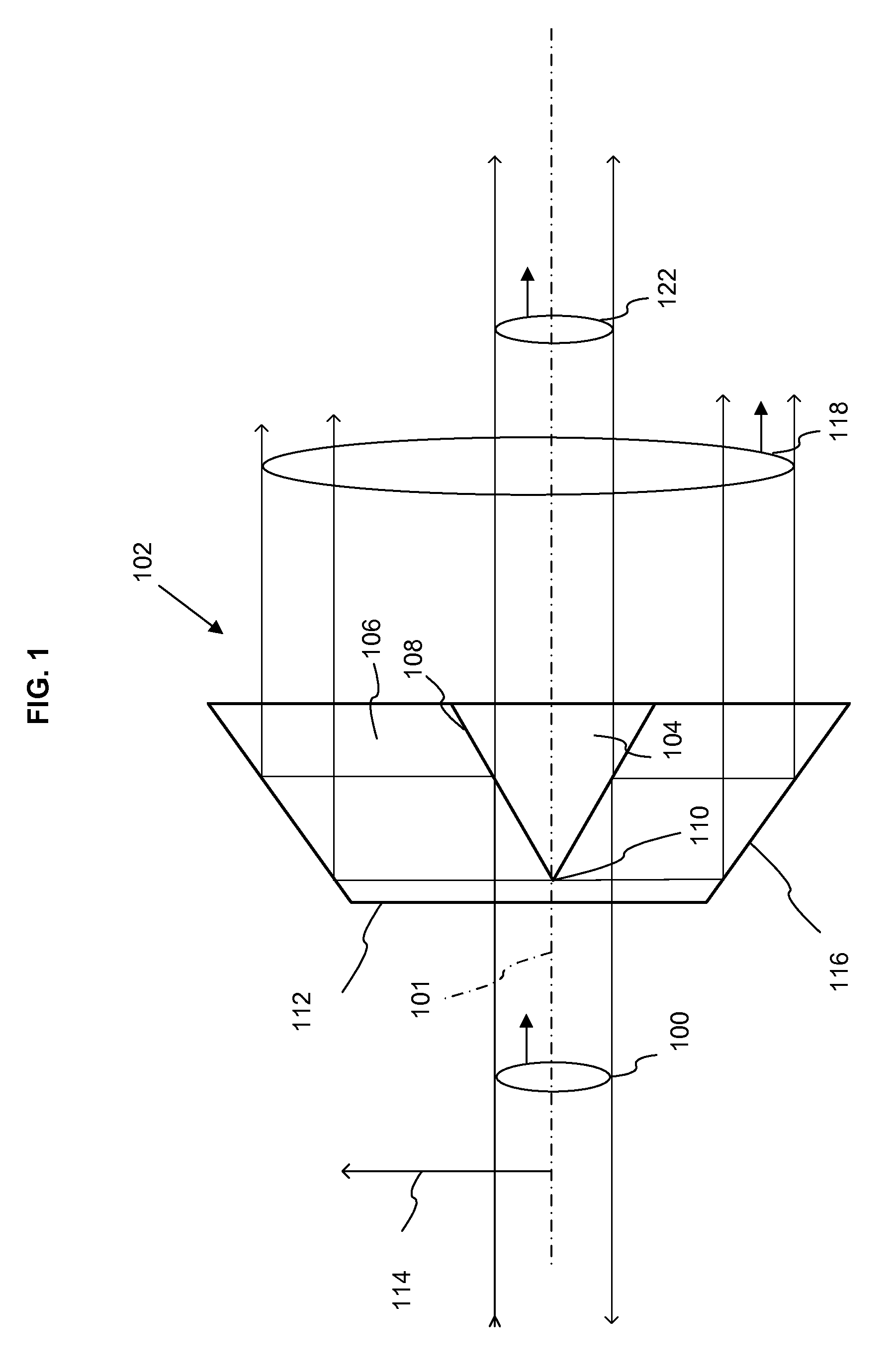
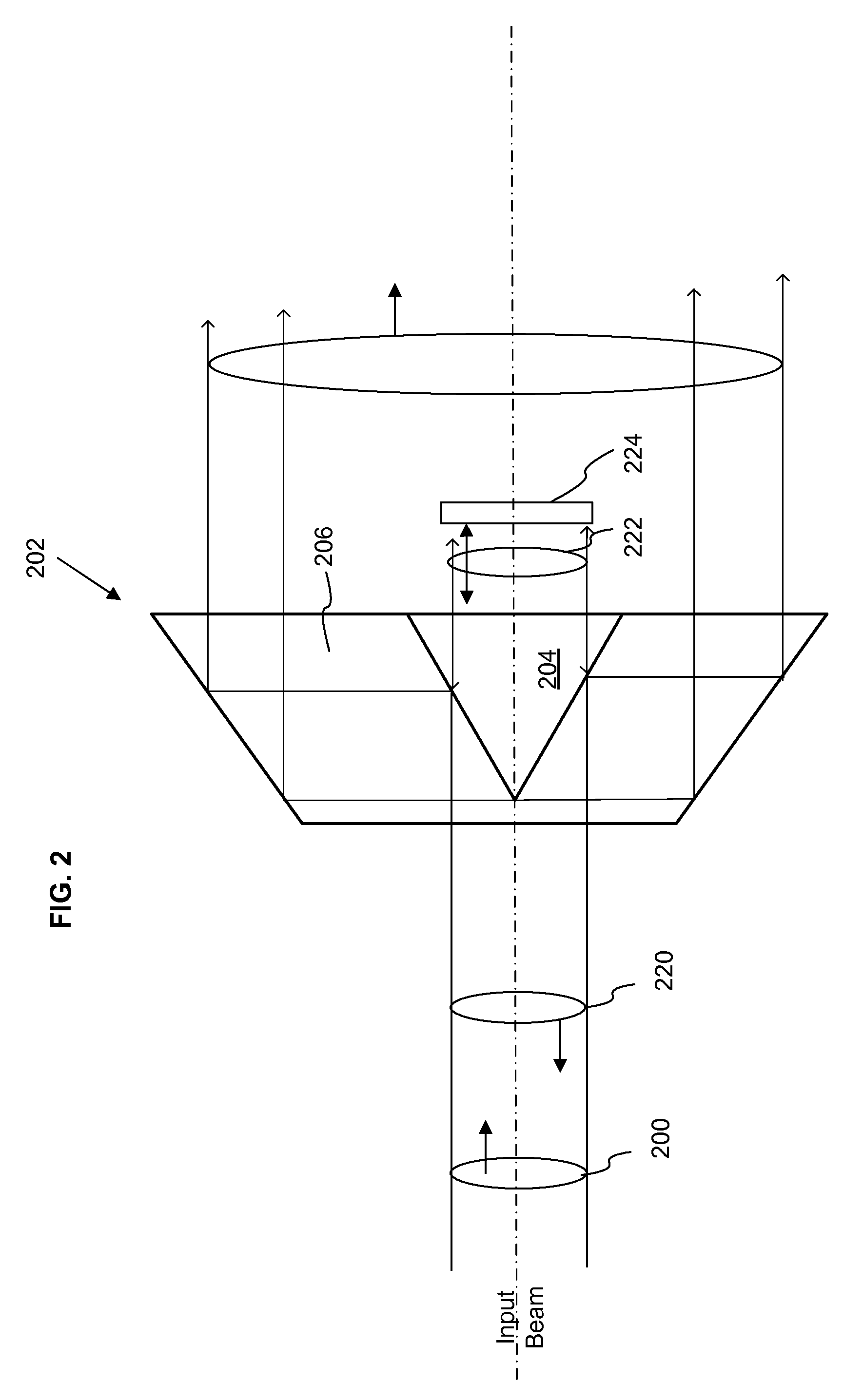
Polarizers and polarizing beam splitter include one or more pairs of axicons that are configured to separate an input beam into a radially polarized component and a tangentially (or azimuthally) polarized component. A second axicon pair can be provided to recombine the tangentially polarized component so as to provide a more uniform beam intensity. The radially polarized component can be reflected or otherwise directed so that one or both the radial and tangential components are available for use.

Description

PRIORITY CLAIM[0001]This application claims the benefit of U.S. Provisional Application No. 61 / 308,202, filed Feb. 25, 2010, which is incorporated by reference herein it its entirety.FIELD[0002]The disclosure pertains to polarizers that produce tangentially and radially polarized beams.BACKGROUND[0003]The state of polarization of an optical beam can be a significant factor in determining the beam's spatial profile, particularly if the optical beam is focused to a small spot using high numerical aperture optics. For example, if a “donut” shaped focused spot is desired having an on-axis null, beam phase must vary in such a way as to destructively interfere on-axis in order to create the null. However, even if beam phase is precisely controlled, destructive interference may not be complete depending on the beam state of polarization. If the optical beam is tangentially polarized, a deep null can be formed. If the optical beam is radially polarized, the beam will have axial components t...

Claims


Application Information

Patent Timeline
IPC IPC(8): G02B27/28
CPCG02B5/001G02B27/283G03F7/70566G03F7/70225G02B27/286
Inventor KNUTSON, JAY R.
Owner US DEPT OF HEALTH & HUMAN SERVICES
Learn More