
Underwater robotic venting and inspection system

a robotic venting and inspection system technology, applied in underwater equipment, special-purpose vessels, greenhouse gas reduction, etc., can solve the problems of difficulty in keeping a freely movable rov in a given position, and achieve the effect of assisting with the inspection of the steam dryer configuration

Active Publication Date: 2012-12-20
WESTINGHOUSE ELECTRIC CORP
View PDF4 Cites 7 Cited by
  • Summary
  • Abstract
  • Description
  • Claims
  • Application Information

AI Technical Summary

Benefits of technology

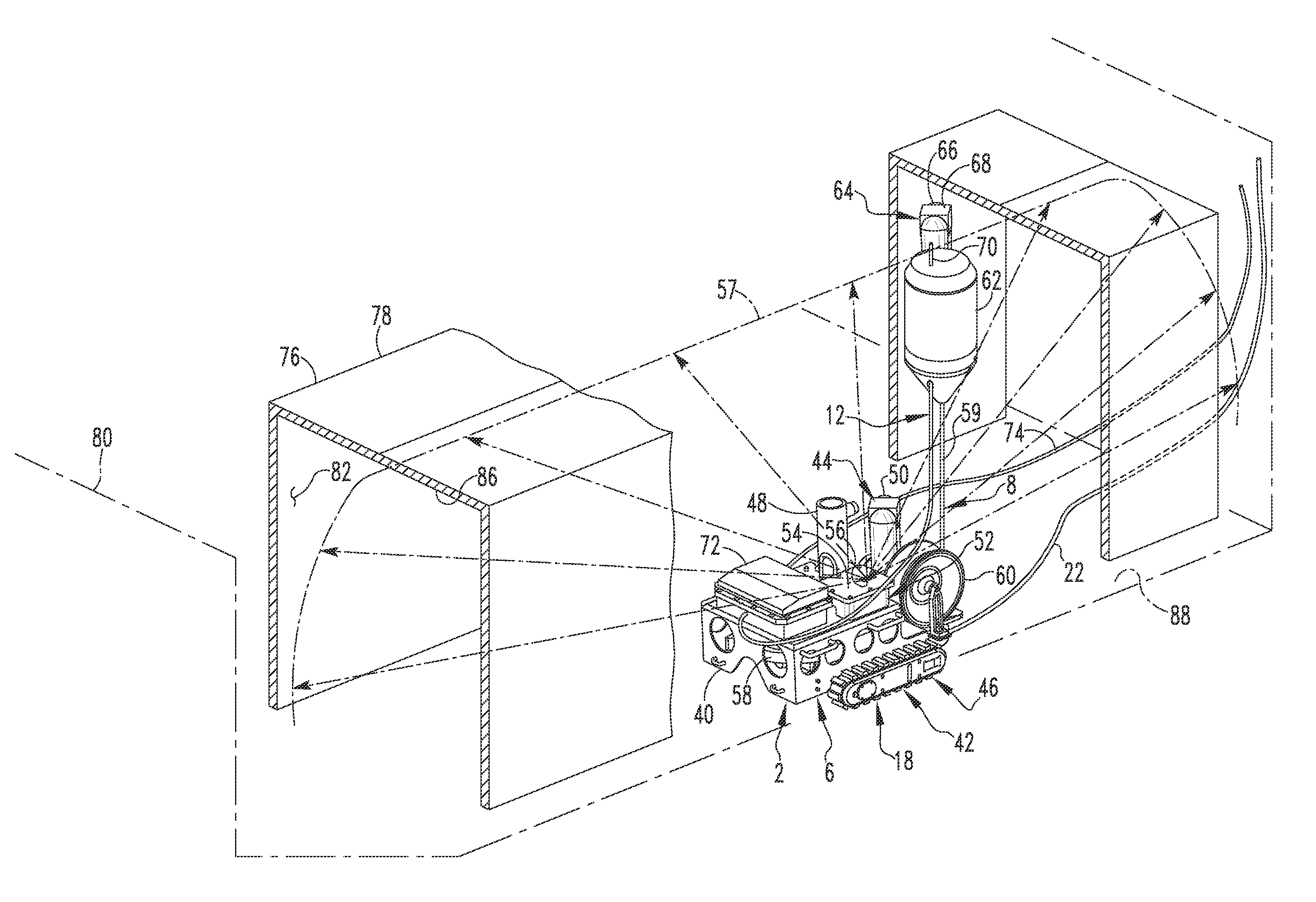
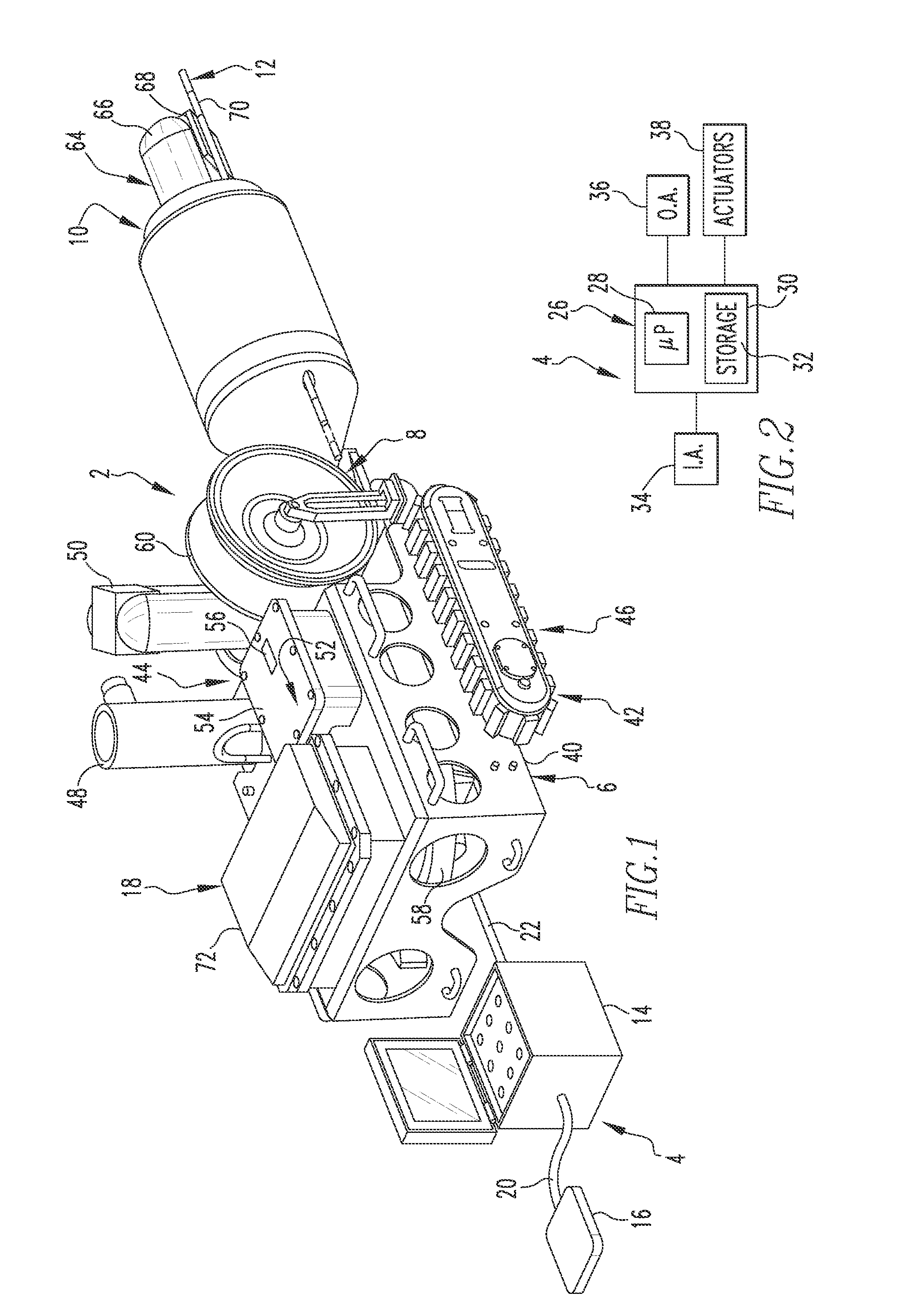
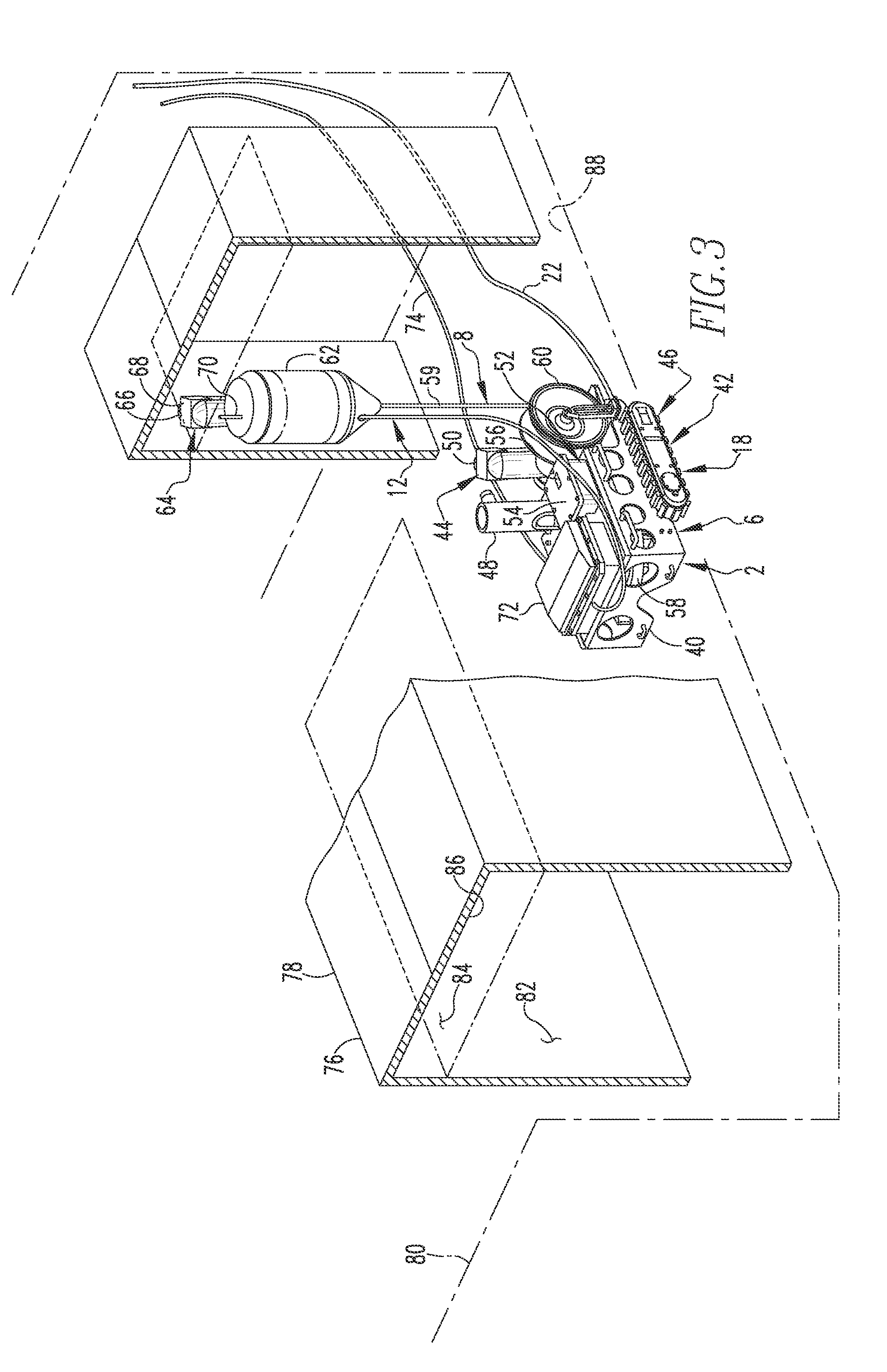
[0007]The present invention provides Inspection and Evaluation (I&E) monitoring capabilities for the various Steam Dryers associated with operating BWRs. This tool assists with the inspection of the steam dryer configurations for different plants when the steam dryer is removed from the reactor vessel and is placed into an equipment pit and is submerged in a fluid such as water. The tool employs an underwater crawler or tractor with an inspection buoy. The crawler drives on the floor of the equipment pit or other structure in a location underneath the steam dryer and deploys a buoy into the upper internal regions of the steam dryer to enable visual inspection of welds, strength members, and the like. The system includes main control device, one underwater crawler with inspection buoy and one interconnection cable for connecting the main control device to the crawler. The system may additionally include a handheld unit that is connected with the main control device by another connection.
[0008]Other aspects of the invention are provided by an improved inspection apparatus, the general nature of which can be stated as including a control apparatus, a tractor apparatus comprising a tractor and a drive mechanism connected together, the drive mechanism being connected with the control apparatus, a tether apparatus disposed on the tractor and being movable between a deployed position and a retracted position, and a buoy apparatus. The buoy apparatus is connected with the tether apparatus and can be generally stated as including a buoy and a camera apparatus, the buoy in a condition submerged in a fluid being structured to apply a buoyant force to the camera apparatus whereby in the deployed position of the tether apparatus the buoy apparatus is in an elevated position situated relatively higher in a vertical direction than in the retracted position of the tether apparatus wherein the buoy apparatus is in another position situated relatively lower in the vertical direction, the camera apparatus being structured to provide a visual output signal to the control apparatus.
[0009]Further aspects of the invention are provided by an improved apparatus structured to vent at least a portion of an air pocket trapped at an underside of an article submerged in a liquid. The general nature of the apparatus can be stated as including a control apparatus, a tractor apparatus that can be stated as including a tractor and a drive mechanism connected together, the drive mechanism being connected with the control apparatus, a tether apparatus disposed on the tractor and being movable between a deployed position and a retracted position, and a buoy apparatus. The buoy apparatus is connected with the tether apparatus and can be generally stated as including a buoy and a vent apparatus, the buoy in a condition submerged in the liquid being structured to apply a buoyant force to at least a portion of the vent apparatus whereby in the deployed position of the tether apparatus the buoy apparatus is in an elevated position situated relatively higher in a vertical direction than in the retracted position of the tether apparatus wherein the buoy apparatus is in another position situated relatively lower in the vertical direction, the at least portion of the vent apparatus being structured to be in fluid communication with the air pocket and to vent at least a portion of the air pocket in the elevated position of the buoy apparatus.

Problems solved by technology

A major challenge to the inspection of steam dryers is that they are in the shape of an inverted can with the “top” being closed.
This can be problematic because of the many obstacles and small spaces created by the internal hardware within the structure, which the vehicle must navigate around with an umbilical trailing behind it.
Moreover, difficulty has been experienced in keeping a freely movable ROV in a given position for a period long enough to inspect a given region with a camera.

Method used


Image

  • Underwater robotic venting and inspection system
  • Underwater robotic venting and inspection system
  • Underwater robotic venting and inspection system

Examples


Embodiment Construction

[0016]An improved inspection and venting apparatus 2 is depicted schematically in FIG. 1 and is depicted at least in part in FIGS. 2-4. The inspection apparatus 2 is advantageously employable to remotely perform visual inspection operations in a submerged environment, such as in an environment where an object is submerged in water or other fluid.

[0017]The inspection apparatus 2 can be said to include a control apparatus 4, a tractor apparatus 6, a tether apparatus 8, a buoy apparatus 10, and a venting apparatus 12. In FIG. 1, the control apparatus 4 is depicted as including a control device 14 and a handheld unit 16. Further in FIG. 1, the tractor apparatus 6, the tether apparatus 8, the buoy apparatus 10, and the venting apparatus 12 together can be said to form a remote portion 18. In the typical application of the inspection apparatus 2, the remote portion 18 is situated and operated in a submerged environment while the control unit 14 and the handheld unit 16 are situated elsewh...


PUM


Abstract

An improved inspection apparatus includes a control apparatus, a tractor apparatus comprising a tractor and a drive mechanism connected together, the drive mechanism being connected with the control apparatus, a tether apparatus disposed on the tractor and being movable between a deployed position and a retracted position, and a buoy apparatus. The buoy apparatus is connected with the tether apparatus and includes a buoy and a camera apparatus, the buoy in a condition submerged in a fluid applying a buoyant force to the camera apparatus whereby in the deployed position of the tether apparatus the buoy apparatus is in an elevated position situated relatively higher in a vertical direction than in the retracted position of the tether apparatus wherein the buoy apparatus is in another position situated relatively lower in the vertical direction, the camera apparatus being structured to provide a visual output signal to the control apparatus.

Description

CROSS-REFERENCE TO RELATED APPLICATION[0001]The present application claims priority from U.S. Provisional Patent Application No. 61 / 478,469 filed Apr. 22, 2011, and entitled UNDERWATER ROBOTIC INSPECTION SYSTEM, the disclosures of which are incorporated herein by reference.FIELD OF THE INVENTION[0002]The present invention relates to a system for inspection of submerged environments, such as can exist with respect to certain structures of nuclear reactors.BACKGROUND OF THE INVENTION[0003]The primary safety consideration in the operation of any nuclear reactor is the control and containment of radioactive material and radioactivity, under both normal and accident conditions. Numerous controls and barriers are installed in nuclear plants to protect workers and the public from the effects of radiation.[0004]Regular inspection of nuclear reactors is essential to avoid catastrophic breakdowns and to properly schedule preventive maintenance procedures. In boiling water reactors (BWRs), one...

Claims


Application Information

Patent Timeline
Patent Type & Authority Applications(United States)
IPC IPC(8): B63G8/00
CPCG21C17/013Y02E30/30
Inventor CONDIT, JEFFHARTMAN, NICHOLASMORA, DYLANLAFFERTY, BRADKNIGHT, KYLEHOGAN, JAMIEPOISSONNET, CYRILEVERETT, STEVE
Owner WESTINGHOUSE ELECTRIC CORP
Learn More