
Encoding/decoding method and apparatus using a tree structure

a tree structure and encoding technology, applied in the field of encoding/decoding methods and apparatus using a tree structure, can solve the problems of reducing the efficiency of video compression, and no such technology has been developed that can effectively compress a large volume of high-resolution videos, and achieve the effect of encoding efficiency and

Active Publication Date: 2012-12-06
SK TELECOM CO LTD
View PDF7 Cites 33 Cited by
  • Summary
  • Abstract
  • Description
  • Claims
  • Application Information

AI Technical Summary

Benefits of technology

[0013]According to the present disclosure as described above, the encoding efficiency and in turn the video compression efficiency may be improved by using a tree structure in the encoding of various pieces of image information and the decoding of the resultant encoded data.

Problems solved by technology

In addition, there is an outstanding necessity for compressing high-resolution videos such as 4K×2K videos, but no such technology has been developed that can effectively compress a large volume of high-resolution videos.
Still, as the video size increases and units of division for encoding a large volume of videos increase, more information is necessary for the intra prediction encoding and inter prediction encoding, resulting in a reduction in the video compression efficiency.

Method used


Image

  • Encoding/decoding method and apparatus using a tree structure
  • Encoding/decoding method and apparatus using a tree structure
  • Encoding/decoding method and apparatus using a tree structure

Examples


first embodiment

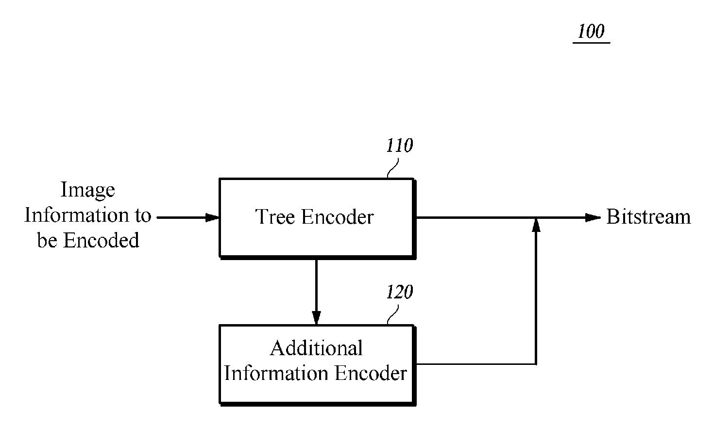
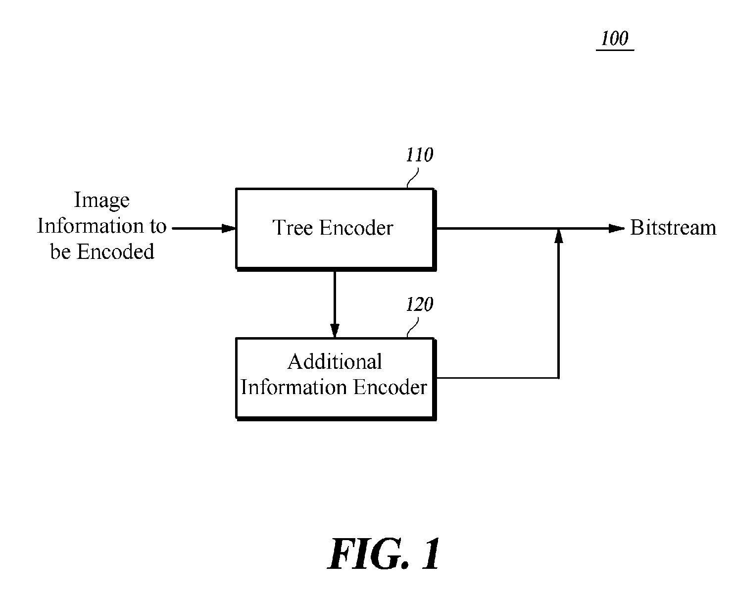
[0034]FIG. 1 is a block diagram schematically showing an encoding apparatus using a tree structure according to the present disclosure.

[0035]An encoding apparatus 100 using a tree structure according to a first embodiment of the present disclosure may include a tree encoder 110 and an additional information encoder 120.

[0036]The tree encoder 110 groups predetermined areas having image information to be encoded into a plurality of groups, generates a node value of each layer up to an uppermost layer by determining a minimum value or a maximum value of information to be encoded within grouped areas as information on the grouped areas, and encodes a difference value between the node value of each layer and a node value of an upper layer or a difference value between the node value of each layer and a value determined based on a preset standard.

[0037]The term “node value of each layer” means a value of information on areas grouped at each layer. For example, the node value at the lowerm...

second embodiment

[0105]FIG. 8 is a block diagram schematically showing an encoding apparatus using a tree structure according to the present disclosure.

[0106]The encoding apparatus 800 using the tree structure according to the second embodiment of the present disclosure may include a tree encoder 810 and an additional information encoder 820 both for variably sized blocks.

[0107]The tree encoder 810 for the variably sized block groups areas having the same information among predetermined areas having the image information to be encoded, and encodes one or more of a node value and a flag for indicating whether or not a node of each layer is divided.

[0108]The additional information encoder 820 for the variably sized block encodes additional information, including information on the maximum number of layers in the tree structure according to the second embodiment and information on the size of area indicated by each node of the lowermost layer. The encoded additional information is included in a header ...


PUM


Abstract

The present disclosure provides an encoding / decoding method using a tree structure. The encoding method for encoding image information includes: grouping predetermined areas having the image information into a plurality of groups, and generating a node value of each layer up to an uppermost layer by determining a minimum value or a maximum value of information to be encoded within grouped areas as information on the grouped areas; and encoding a difference value between the node value of each layer and a node value of an upper layer or a difference value between the node value of each layer and a value determined based on a preset criterion. Accordingly, the encoding efficiency and in turn the video compression efficiency are improved by using the tree structure in the encoding of various pieces of image information and the decoding of the resultant encoded data.

Description

TECHNICAL FIELD[0001]The present disclosure relates to an encoding / decoding method and apparatus using a tree structure. More particularly, the present disclosure relates to a method and apparatus for improving the encoding efficiency and in turn the video compression efficiency by using a tree structure in the encoding of various pieces of image information and the decoding of the resultant encoded data.BACKGROUND[0002]The statements in this section merely provide background information related to the present disclosure and may not constitute prior art.[0003]Current video data compression technologies include H.261, H.263, MPEG-2, MPEG-4, and the like. In encoding images, the existing video compression technologies divide each image into fixedly sized macroblocks which are composed of rectangular 16×16 pixel areas of luma component and rectangular 8×8 pixel areas of chroma component. All of the luma and chroma components are spatially or temporally predicted, and the resultant pred...

Claims


Application Information

Patent Timeline
Patent Type & Authority Applications(United States)
IPC IPC(8): G06K9/36
CPCH04N19/00H04N19/463H04N19/96H04N19/61H04N19/44H04N19/85H04N19/105H04N19/119H04N19/146H04N19/176H04N19/46H04N19/60
Inventor KIM, SUNYEONLIM, JEONGYEONCHOI, JAEHOONLEE, GYUMINMOON, JOOHEELEE, YUNGLYULKIM, HAEKWANGJEON, BYEUNGWOOHAN, JONGKIKIM, DONGWON
Owner SK TELECOM CO LTD
Learn More