Bead roller

a technology of bead rollers and rollers, which is applied in the field of bead rollers, can solve the problems of too expensive to utilize a number of different presses to model different sheet details, and achieve the effect of increasing the number of operations and increasing the maneuverability of work pieces

Inactive Publication Date: 2012-12-06
JANSSON LARS
View PDF6 Cites 2 Cited by
  • Summary
  • Abstract
  • Description
  • Claims
  • Application Information

AI Technical Summary

Benefits of technology

[0011]A substantial advantage of the present invention in relation to corresponding Prior Art machines is the increased maneuverability for work pieces when profile on a sheet plate work piece is to be carried out.
[0012]By the arrangement of a substantially greater maneuvering space between the drive shafts of the dies as described below, according to the present invention, possibilities to perform the sheet working on sheet work pieces having strong curvatures in a plane common to the plane through both drive shafts can be achieved. By this is meant that a drive shaft, as in a conventional arrangement, will not be a hindrance for the forwarding of said sheet work piece between the dies. Where profiles on sheets are to be effected, the inventive machine allows a substantially increased number of operations to be accomplished compared to what has been possible by use of current and conventional bead rollers.
[0013]The inventive bead roller is characterized by that the major part of the surfaces of the two arms facing each other and enclosing the drive shafts driving the dies are located at a greater distance from each other than the distance between the outermost ends of the drive shafts. It should be noted here that the term: “the outermost ends of the drive shafts” refers to the ends on which dies are mounted. Further, by said distance is meant the shortest distance between the surfaces of the drive shafts at said outermost ends.

Problems solved by technology

On the other hand, if vehicles like cars or motor bikes are manufactured in solitary numbers, it would be too costly to utilize a number of different presses to model different sheet details, for example details of the coach of a car, fenders of a motor bike, etc.

Method used


Image

  • Bead roller
  • Bead roller
  • Bead roller

Examples


Embodiment Construction

[0025]Below, a number of variants of embodiments of the invention are described and supported by the accompanying Figures.

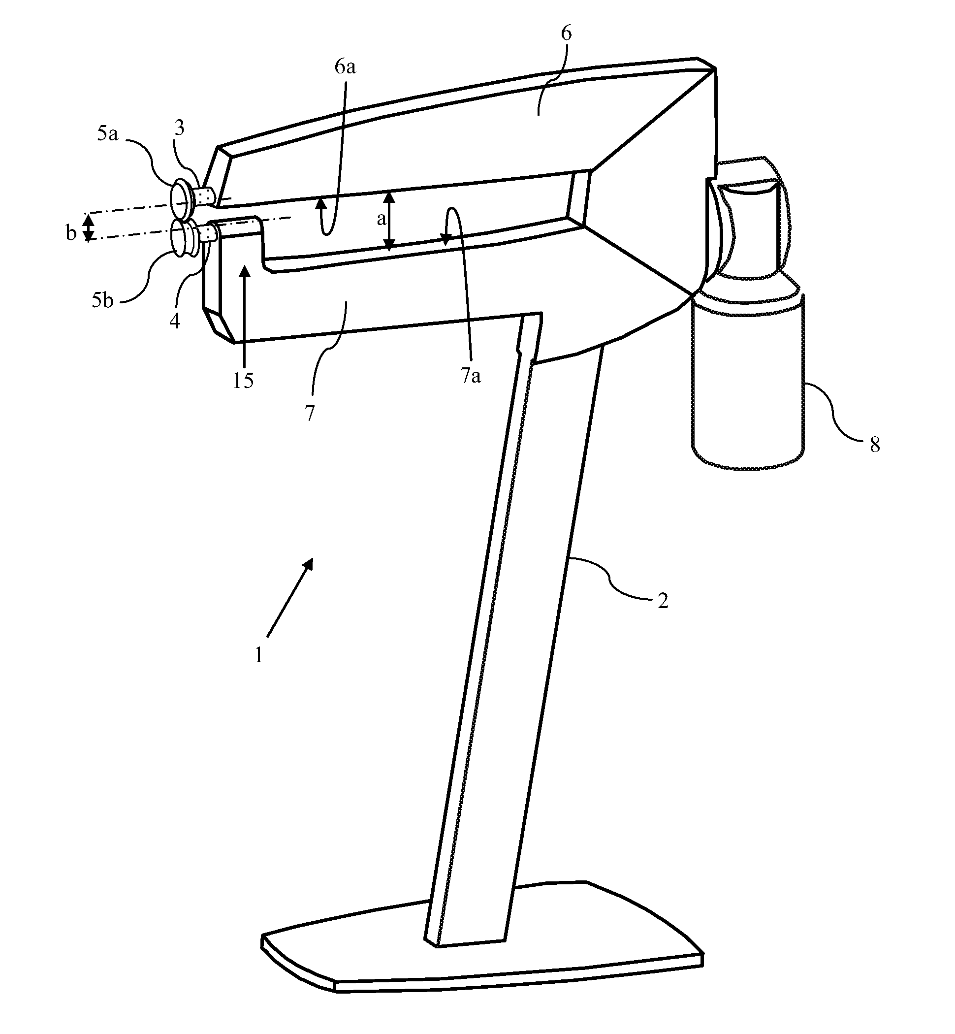
[0026]FIG. 4 is a perspective view of a floor model of a bead roller 1 according to a first embodiment of the present invention. It should here, furthermore, be mentioned that details having correspondence to details of prior art designs of bead rollers, as described above, are referred to by use of the same final Figures, but details for the Prior Art machines being numbered starting from reference number 101 to avoid confusion. From the Figure it is evident that a floor stand is denoted by 2. Upper and lower arms are denoted by 6 and 7, respectively. Drive shafts 3, 4 are supported by, usually enclosed by and carried in bearings by the arms 6, 7, where said drive shafts 3, 4 are located in a plane common to both drive shafts in a manner as described below. A drive unit 8, here represented by an electric motor, is utilized to run the drive shafts. Instead of the...


PUM

PropertyMeasurementUnit
distanceaaaaaaaaaa
angleaaaaaaaaaa
rotational movementaaaaaaaaaa

Abstract

A bead roller sheet metal working machine (1) comprising a first drive shaft (3) and a second drive shaft (4) arranged in a plane common to both drive shafts (3, 4), wherein both drive shafts (3, 4) at their respective inner ends are driven by means of a drive unit (8) which by a first transmission (13) drives said drive shafts (3, 4) to rotate in opposite rotational directions, and where said drive shafts (3, 4) at their respective outer ends are equipped with dies (5a, 5b) by means of which said sheet can be provided with beads when the sheet is forwarded between the dies (5a, 5b) along a plane substantially tangential and common to both dies, and where a greater part of mutually facing surfaces (6a, 7a) of two arms (6, 7) carrying the drive shafts (3, 4) are located at a greater distance (a) from one another than a distance (b) between the outermost ends of the drive shafts to allow a curved work piece access to the machine while working.

Description

CROSS-REFERENCE TO RELATED APPLICATIONS[0001]The present application claims foreign priority from Swedish Application No. SE1100430-6 filed on Jun. 1, 2011, and incorporated herein by reference.FIELD OF THE INVENTION[0002]The present invention relates to a bead roller for use in connection with sheet metal working, where a thin sheet can be shaped and provided with beads by feeding the sheet between dies of the machine.BACKGROUND OF THE INVENTION[0003]Bead rollers are used in techniques for sheet metal shaping to achieve stiffening of sheets, to model a sheet metal to a desired structure or to design a sheet as desired. The stiffening or the design is accomplished by providing the sheet with profiles, such as beads in the form of notches, steps or ridges, which may be linear or curved as desired, along the sheet.[0004]In the automotive industry there are a lot of sheet details which may have to be shaped into different designs. With regard to types of vehicles manufactured in series...

Claims


Application Information

Patent Timeline
Patent Type & Authority Applications(United States)
IPC IPC(8): B21D5/14
CPCB21D17/04
Inventor WALLINDER, JONAS
Owner JANSSON LARS
Why Eureka
Try Eureka