
Driver assistance system

a technology of assistance system and driver, applied in the direction of navigation instruments, process and machine control, instruments, etc., can solve the problems of inability to detect signs in complex environment, inability to use visual and inability to use optical sensors to detect speed or no-passing zone warning

Inactive Publication Date: 2012-11-29
TK HLDG
View PDF6 Cites 230 Cited by
  • Summary
  • Abstract
  • Description
  • Claims
  • Application Information

AI Technical Summary

Benefits of technology

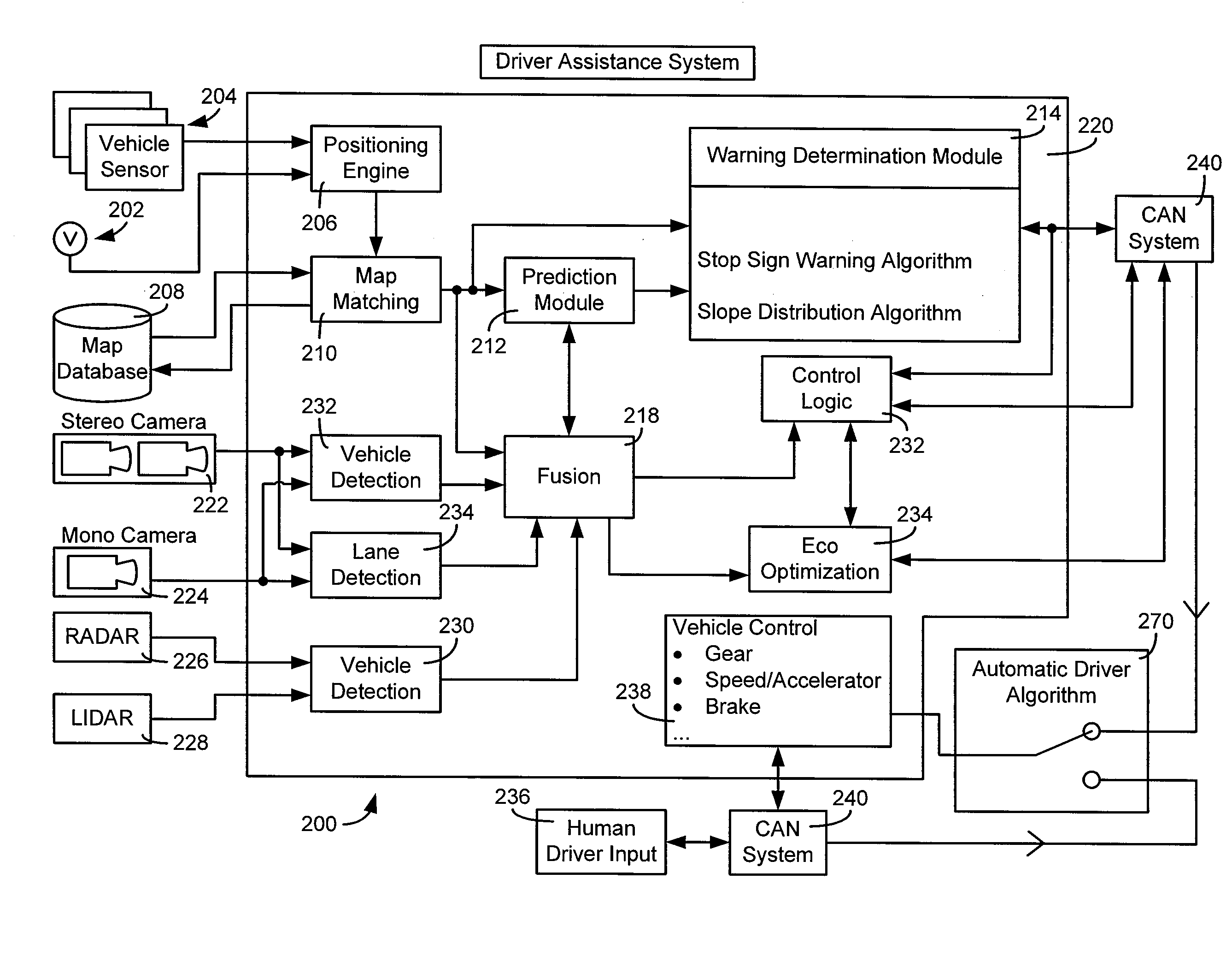
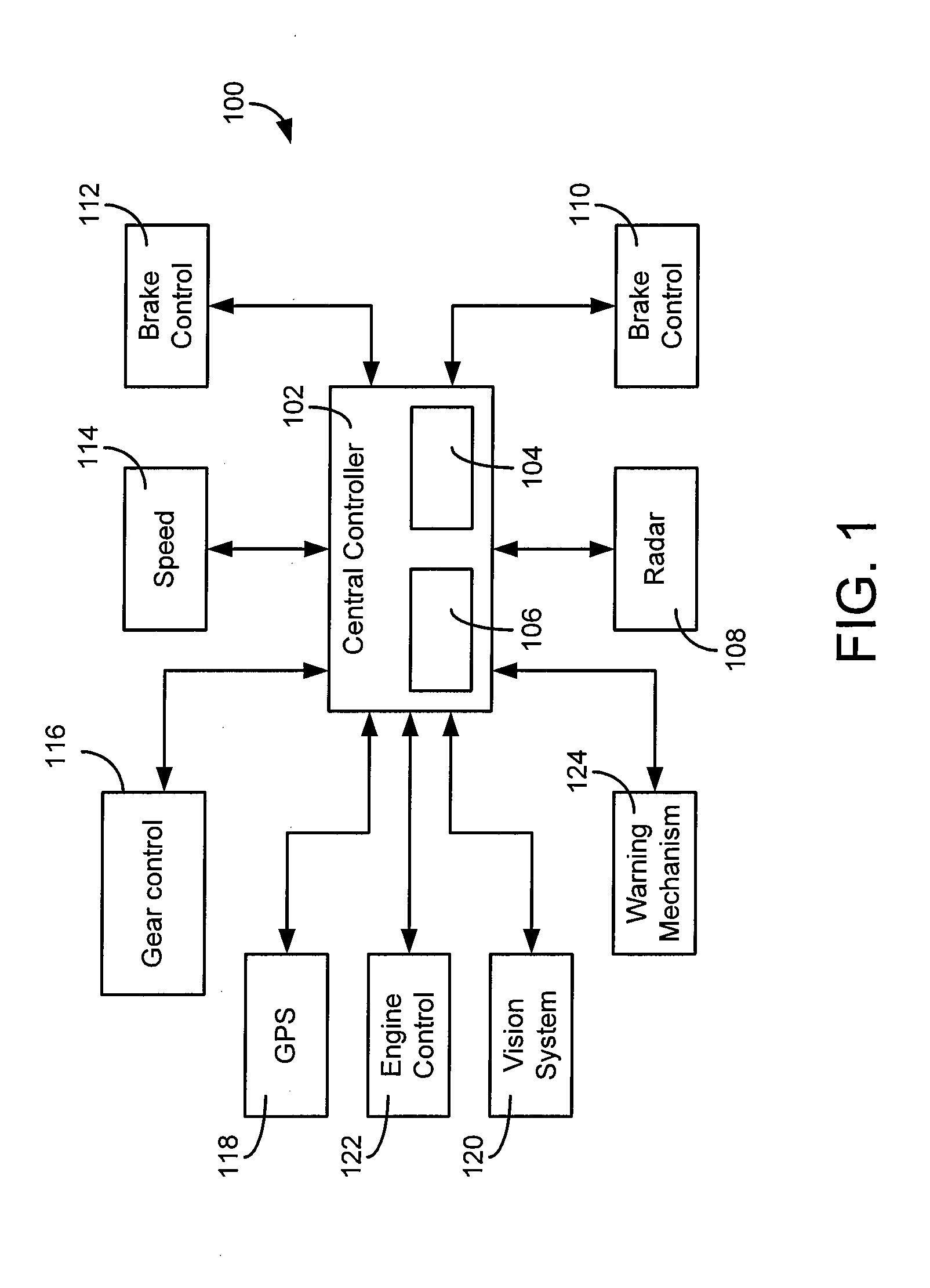
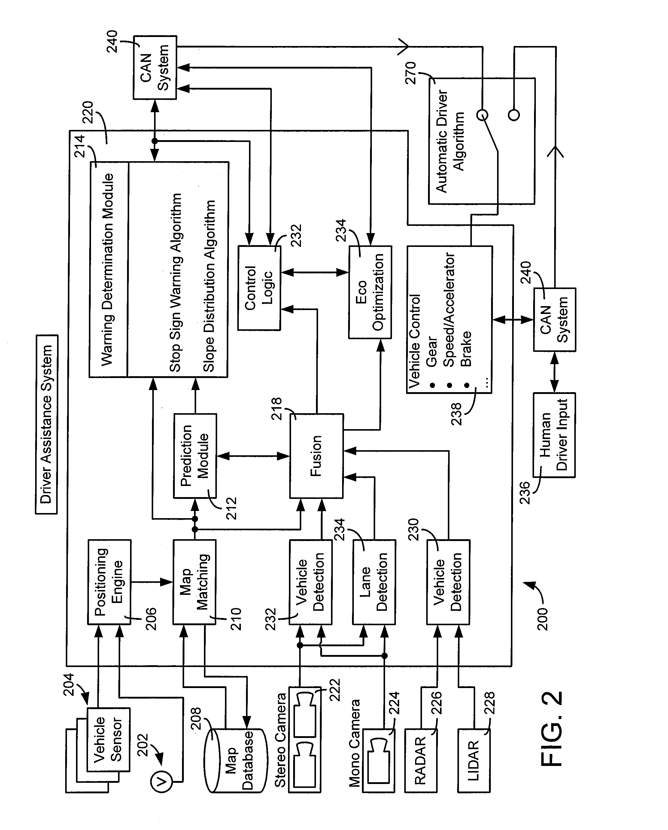
[0005]According to an exemplary embodiment, a driver assistance system includes a map database comprising a map database comprising navigation characteristics related to road locations, a GPS unit that receives location data of the vehicle, a map matching module configured to receive the location data of the vehicle and retrieve navigation characteristics relevant to the location data using a processing circuit, a prediction module configured to generate a most probable future path for the vehicle and to determine a location of at least one navigation characteristic with respect to the most probable future path and the vehicle, at least one vehicle sensor unit configured to generate vehicle data, and a warning module configured to transmit a control signal to a vehicle cont

Problems solved by technology

Like most vision systems, optical sensor based zone warning inevitably suffers from adverse illumination and weather conditions when the assistance is needed most.
A method of detecting speed or no-passing zone warning using visual sensors suffers from several limitations.
The visual sensors can fail to detect signs in complex environment (e.g., downtown streets).
The visual sensors can also fail to detect signs because of different sign shape and location.
The visual sensors can also incorrectly recognize speeds because of misclassification at high speeds.
The visual sensors can also suffer from degraded detection / recognition at night, in rain or snow, when facing low angle sunlight (e.g., at dawn or dusk).

Method used


Image

  • Driver assistance system
  • Driver assistance system
  • Driver assistance system

Examples


Embodiment Construction

[0016]Before describing in detail the particular improved system and method, it should be observed that the several disclosed embodiments include, but are not limited to a novel structural combination of conventional data and / or signal processing components and communications circuits, and not in the particular detailed configurations thereof. Accordingly, the structure, methods, functions, control and arrangement of conventional components and circuits have, for the most part, been illustrated in the drawings by readily understandable block representations and schematic diagrams, in order not to obscure the disclosure with structural details which will be readily apparent to those skilled in the art, having the benefit of the description herein. Further, the disclosed embodiments are not limited to the particular embodiments depicted in the exemplary diagrams, but should be construed in accordance with the language in the claims.

[0017]In general, according to various exemplary embo...


PUM


Abstract

A system and method of assisting a driver of a vehicle by providing driver and vehicle feedback control signals is disclosed. The system and method includes receiving location data of the vehicle from a GPS unit, receiving the location data of the vehicle and retrieving navigation characteristics relevant to the location data using a processing circuit, generating a most probable future path for the vehicle and determining a location of at least one navigation characteristic with respect to the most probable future path and the vehicle, generating vehicle data at least one vehicle sensor, and transmitting a control signal to a vehicle control area network to warn the driver of an upcoming navigation characteristic on the most probable path.

Description

CROSS-REFERENCE TO RELATED PATENT APPLICATIONS[0001]This application claims priority from Provisional Application U.S. Application 61 / 466,870, filed Mar. 23, 2011, incorporated herein by reference in its entirety. This application also claims priority from Provisional Application U.S. Application 61 / 466,873, filed Mar. 23, 2011, incorporated herein by reference in its entirety. This application also claims priority from Provisional Application U.S. Application 61 / 466,880, filed Mar. 23, 2011, incorporated herein by reference in its entirety.BACKGROUND OF THE INVENTION[0002]Driver assistance systems are becoming more and more prevalent in vehicles. Driver assistance systems can help a driver deal with an upcoming road hazard condition, whether it be an upcoming acute curve in the road or an accident that has occurred in a portion of the road in which the driver is driving towards.[0003]Navigation warning systems alert the driver when various driving events on a segment of road the ve...

Claims


Application Information

Patent Timeline
IPC IPC(8): G06F17/00G01C21/26
CPCB60W10/06Y02T10/84B60W30/143B60W30/18109B60W50/0097B60W50/14B60W50/16B60W2050/143B60W2050/146B60W2510/1005B60W2520/10B60W2550/22B60W2550/402B60W2720/106B60Y2300/18158B60W10/184B60W2555/60B60W2556/50
Inventor COOPRIDER, TROY OTISSCHMIDLIN, MICHAEL J.IBRAHIM, FAROOGVEMPATY, PAVAN K.
Owner TK HLDG
Learn More