
System and Method for Correcting Astigmatism Caused by an Aircraft Canopy

Inactive Publication Date: 2012-11-22
ELBIT SYSTEMS OF AMERICA LLC
View PDF5 Cites 5 Cited by
  • Summary
  • Abstract
  • Description
  • Claims
  • Application Information

AI Technical Summary

Benefits of technology

[0004]Particular embodiments of the present invention may provide one or more technical advantages. For example, certain embodiments may be configured to dynamically compensate for varying astigmatism caused by an aircraft canopy in real-time as the viewing angle of an imaging system within the aircraft cockpit changes. Alternative embodiments may be configured to fine-tune astigmatic correction for imaging systems permanently fixed within the cockpit of an aircraft or other vehicle.

Problems solved by technology

Certain types of aircraft canopies, however, may refract light rays in such a way as to cause astigmatism for an optical system imaging those refracted light rays.

Method used


Image

  • System and Method for Correcting Astigmatism Caused by an Aircraft Canopy
  • System and Method for Correcting Astigmatism Caused by an Aircraft Canopy

Examples


Embodiment Construction

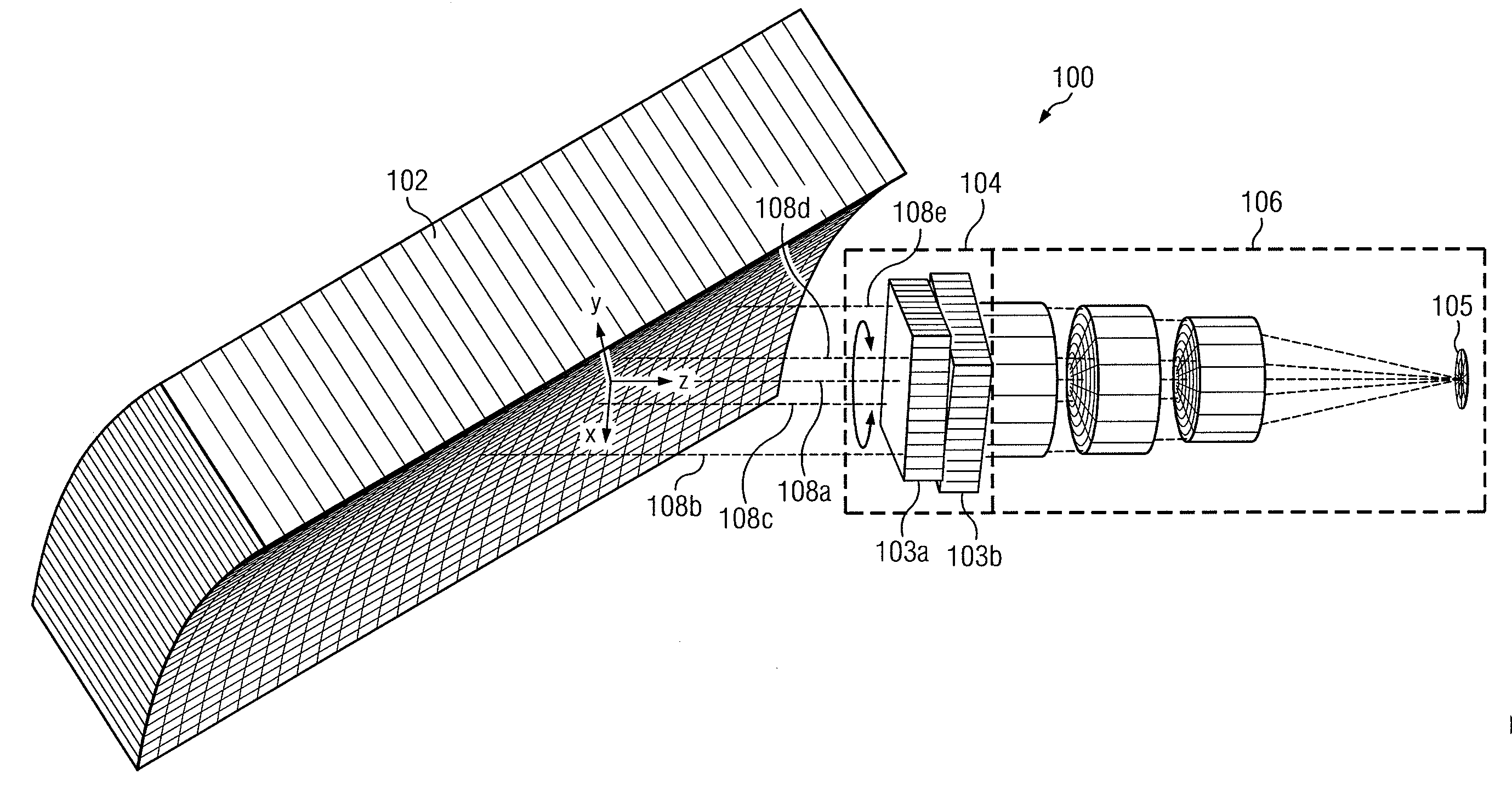
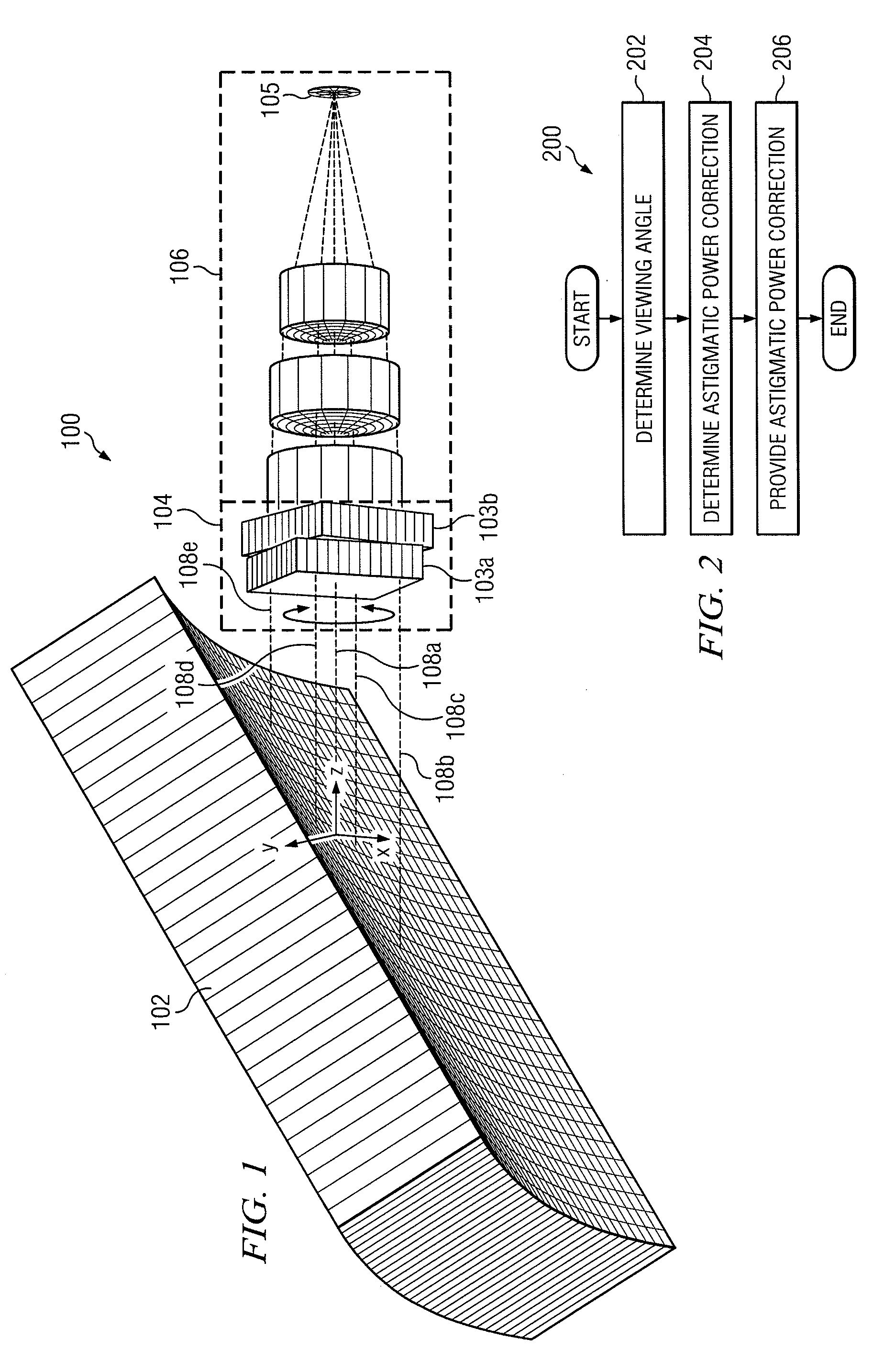
[0009]According to certain embodiments of the present disclosure, a system and method are provided for correcting astigmatism caused by an aircraft canopy. For example, the light received by certain imaging systems in a cockpit of an aircraft may be modulated by adjusting its astigmatic power to correct astigmatism caused by the aircraft canopy. In certain embodiments, this adjustment can be done on a one time basis to fine tune high resolution cameras that are fixed in the cockpit. In alternative embodiments, the adjustment can be done on a continuous basis based at least in part on a determination of the real-time viewing angle of the imaging system through the aircraft canopy. For example, particular embodiments may be a part of a helmet mounted display system, such that different portions of an aircraft canopy may be included in the optical path of an imaging system as the helmet wearer moves his or her head. The astigmatism caused by an aircraft canopy may vary, however, as a f...


PUM


Abstract

In a method embodiment, a method for correcting astigmatism caused by an aircraft canopy comprises receiving at a compensator module a plurality of light rays that have been refracted by an aircraft canopy. At least two of the refracted light rays have respective foci different from one another and propagate in respective planes that are substantially perpendicular to one another, such that astigmatism occurs. The method further includes using the compensator module to substantially compensate for the astigmatism by providing astigmatic power to the received plurality of light rays. The method also includes providing the plurality of light rays having the astigmatic power compensation to an imaging module. The imaging module is configured to generate imagery using the plurality of light rays having the astigmatic power compensation.

Description

TECHNICAL FIELD[0001]This invention relates generally to imaging systems, and more particularly to a system and method for correcting astigmatism caused by light transmissive structures having irregular or tonic curvatures, such as an aircraft canopy.BACKGROUND[0002]Optical systems are sometimes used to image light rays transmitted through an aircraft canopy or through other structures having irregular or tonic curvatures. In certain instances, for example, pilots may use certain electro-optical systems in tactical aircraft to view night-vision imagery through an aircraft canopy. Certain types of aircraft canopies, however, may refract light rays in such a way as to cause astigmatism for an optical system imaging those refracted light rays. The form and magnitude of astigmatism caused by an aircraft canopy may vary at times depending on which of several possible optical paths the optical system may be capable of imaging. For example, the front of an aircraft canopy may cause an asti...

Claims


Application Information

Patent Timeline
IPC IPC(8): G02B13/14G02B27/00
CPCG02B27/0025G02B2027/011G02B27/0101
Inventor HARDER, JAMES A.SPRAGUE, MICHAELENE W.
Owner ELBIT SYSTEMS OF AMERICA LLC
Learn More