Patient Lift Device

a patient and lift technology, applied in the field of patient lift devices, can solve the problems of health care workers and their patients facing problems related to lifting and moving non-ambulatory patients, patients as well as being subject to potential injuries in lifting such patients,

Inactive Publication Date: 2012-11-22
AMERICAN SLING & ELEVATOR
View PDF12 Cites 12 Cited by
  • Summary
  • Abstract
  • Description
  • Claims
  • Application Information

AI Technical Summary

Benefits of technology

[0005]The present invention entails a device for lifting and moving a patient with respect to a bed, wheelchair, table, or the floor. The patient lift device includes a generally arched superstructure supported on mobile trolleys. The superstructure includes a lifting beam supported by a pair of variable height columns. The lifting beam carries a suspensory trolley for suspending a sling holding a patient. The suspensory trolley is movable along the beam to laterally position the patient while the variable height columns provide vertical patient movement.

Problems solved by technology

Health care workers and their patients face problems related to lifting and moving non-ambulatory patients.
Health care workers face possibilities of injuries to themselves in lifting such patients.
Patients as well are often subjected to potential injuries in the process of being lifted and moved.
Additionally, extant devices and systems for assisting or facilitating the lifting and moving of such patients often subject the patient to disconcerting fear as well as humiliation.
Being, for example, slung under a hoist with lifting cranks or motors suspended overhead is often a source of fear.
Moreover, such extant devices often include configurations that are ungainly to use, difficult to move through doorways and negotiate past obstacles, and bulky to store.

Method used


Image

  • Patient Lift Device
  • Patient Lift Device
  • Patient Lift Device

Examples


Embodiment Construction

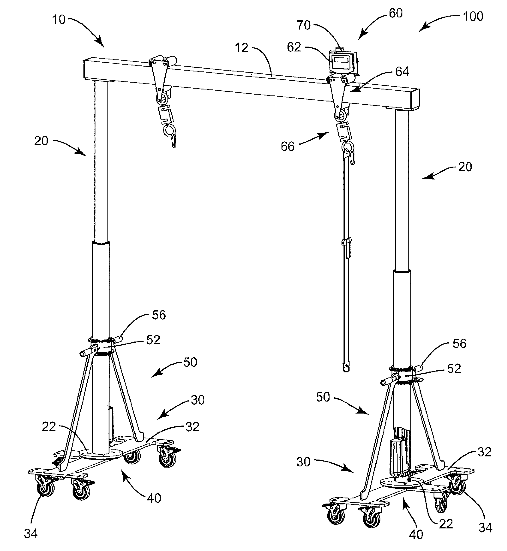
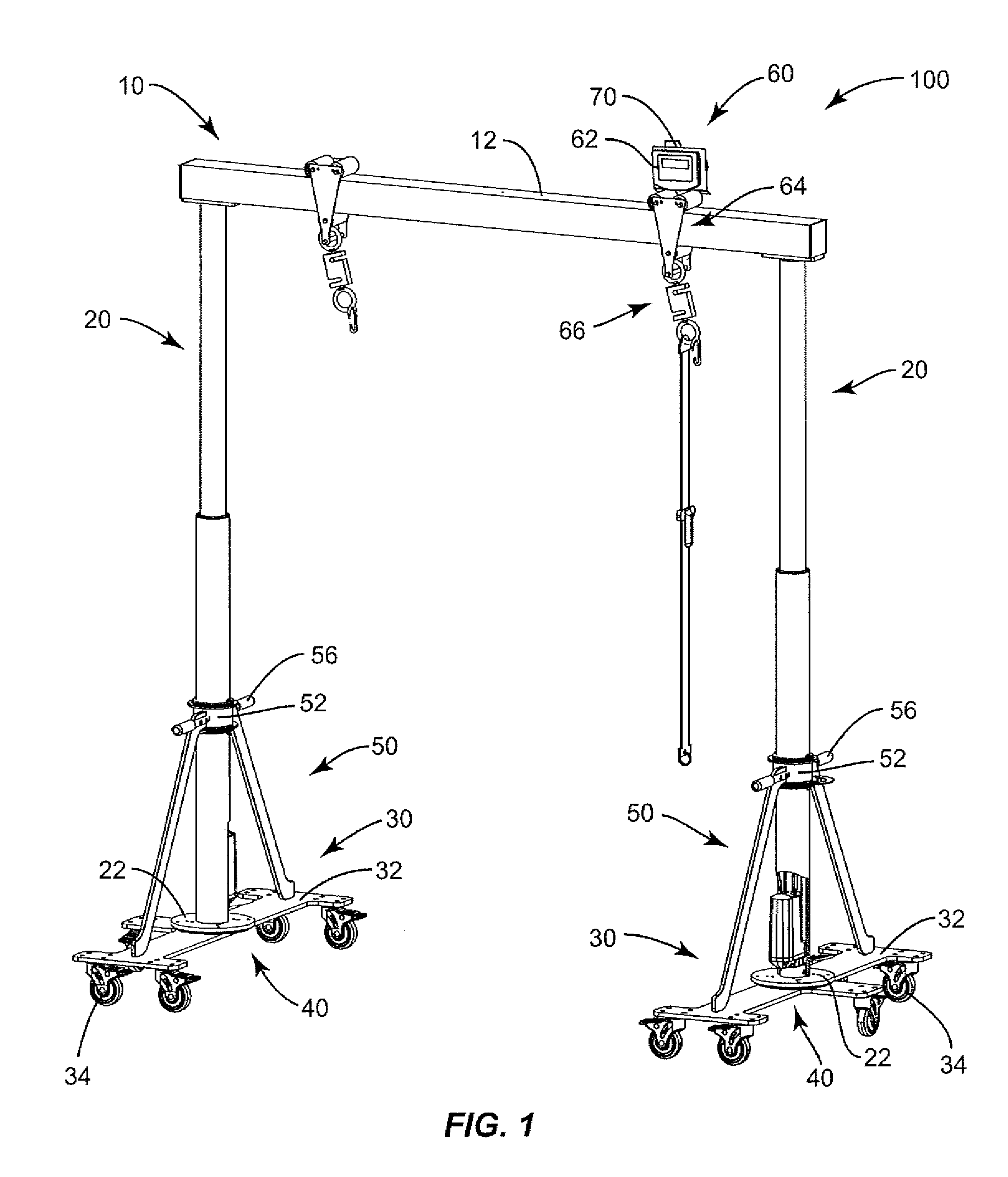
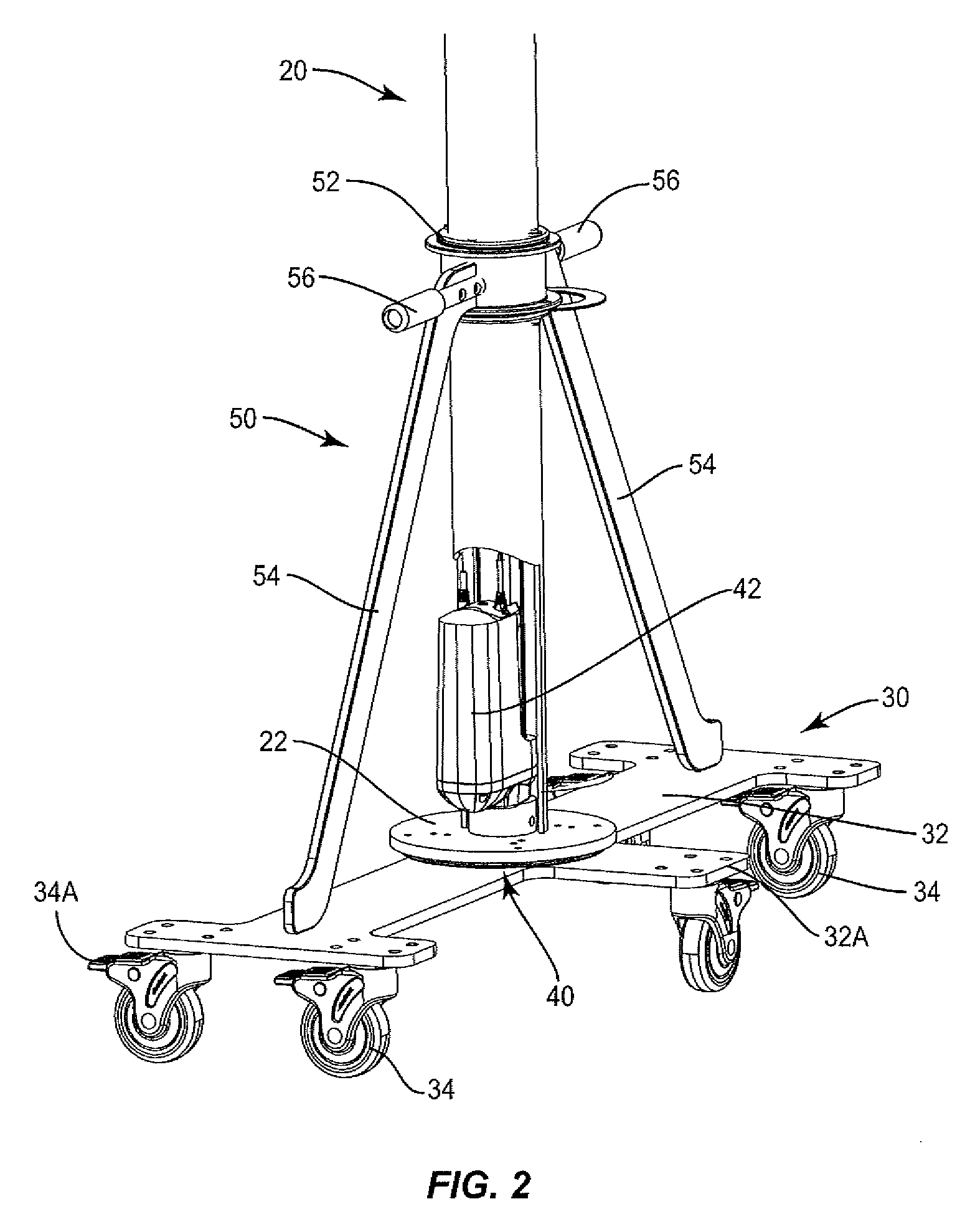
[0019]The present invention entails a patient lift device, indicated generally by the numeral 100 and illustrated generally in FIG. 1. Patient lift device 100 comprises an arched superstructure that is movable over a generally horizontal surface. In particular, the patient lift device 100 comprises an upper support structure 10 interconnected with and supported by a pair of support or vertical lift columns 20. Each support column 20 rests upon a transport trolley 30. Upper support structure 10 includes a cross beam or bar 12, with each end thereof supported on a respective one of the support columns 20. Each support column 20 is connected to a lifting drive assembly or lift actuator 40. Riding on cross beam 12 is a suspensory trolley 60 from which a patient may be suspended as will be described herein. Once suspended, the patient may be lifted and laterally moved by actuating the drive assemblies 40 to raise cross beam 12.

[0020]Each transport trolley 30 includes a generally elongate...


PUM


Abstract

A patient lifting and transfer device is shown which includes a pair of vertical columns having a horizontal bar connected between the two columns. There is provided a mobile support that is rotatively mounted to the lower portion of each vertical column. Each mobile support is elongated and rotatable from a first position where the elongated mobile support extends generally perpendicular to the horizontal bar to a second position where the mobile supports extend generally parallel to the horizontal bar. In the second position, the patient lifting and transport device is relatively narrow and can be moved through close quarters and also stored in relatively small areas.

Description

CROSS REFERENCE TO RELATED APPLICATION[0001]This application claims priority under 35 U.S.C. §119(e) from the following U.S. provisional application: Application Ser. No. 61 / 373,066 filed on Aug. 12, 2010. That application is incorporated in its entirety by reference herein.FIELD OF THE INVENTION[0002]The present invention relates to lifting and moving patients. The present invention also entails a patient lifting and transfer device comprising a pair of vertical columns having a horizontal bar connected between the two columns. In addition, there is provided a mobile support that is rotatably mounted to the lower portion of each vertical column. Each mobile support is elongated and rotatable from a first position where the elongated mobile support extends generally perpendicular to the horizontal bar to a second position where the mobile supports extend generally parallel to the horizontal bar. In the second position, the patient lifting and transport device is relatively narrow an...

Claims


Application Information

Patent Timeline
Patent Type & Authority Applications(United States)
IPC IPC(8): A61G7/10
CPCA61G7/1019A61G7/1042A61G2203/72A61G2203/44A61G7/1046
Inventor MARTIN, WILLIS E.BARR, RODNEY
Owner AMERICAN SLING & ELEVATOR
Why Eureka
Try Eureka