
Manufacturing method for pneumatic tire

a manufacturing method and tire technology, applied in the field of pneumatic tire manufacturing methods, can solve the problems of bare (b) being prone to arise, insufficient absorption of compressional force during vulcanization, and pneumatic tire deformation, etc., to achieve large compressive force, suppress sidewall rubber edge deformation, and increase the thickness of the bead portion

Inactive Publication Date: 2012-11-15
SUMITOMO RUBBER IND LTD
View PDF12 Cites 3 Cited by
  • Summary
  • Abstract
  • Description
  • Claims
  • Application Information

AI Technical Summary

Benefits of technology

[0008]It is therefore, in view of the above-mentioned problems, an object of the present invention to provide a manufacturing method for pneumatic tire capable of suppressing a bare arising near a sidewall rubber edge and improving durability. The present invention is based on arranging an insulation rubber having an adherence property superior to an inner liner between a carcass and an inner liner and turned up around a bead core, disposing a sidewall rubber edge more inward in the tire radial direction than the bead core, and terminating an outer edge of the turn-up part of the insulation rubber more outward in the tire radial direction than the sidewall rubber edge.Means of Solving the Problems
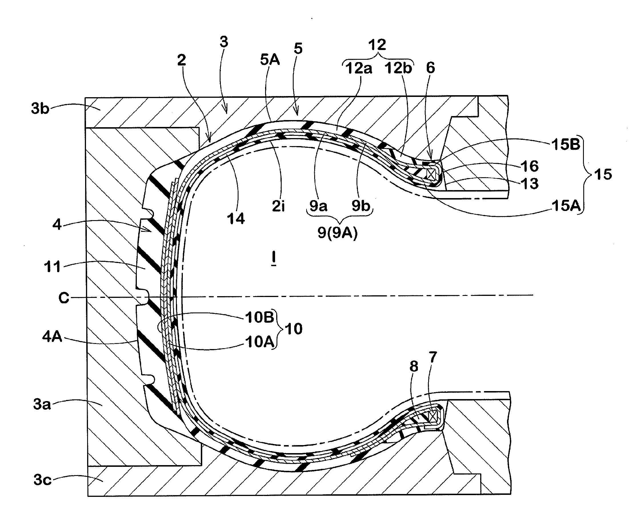
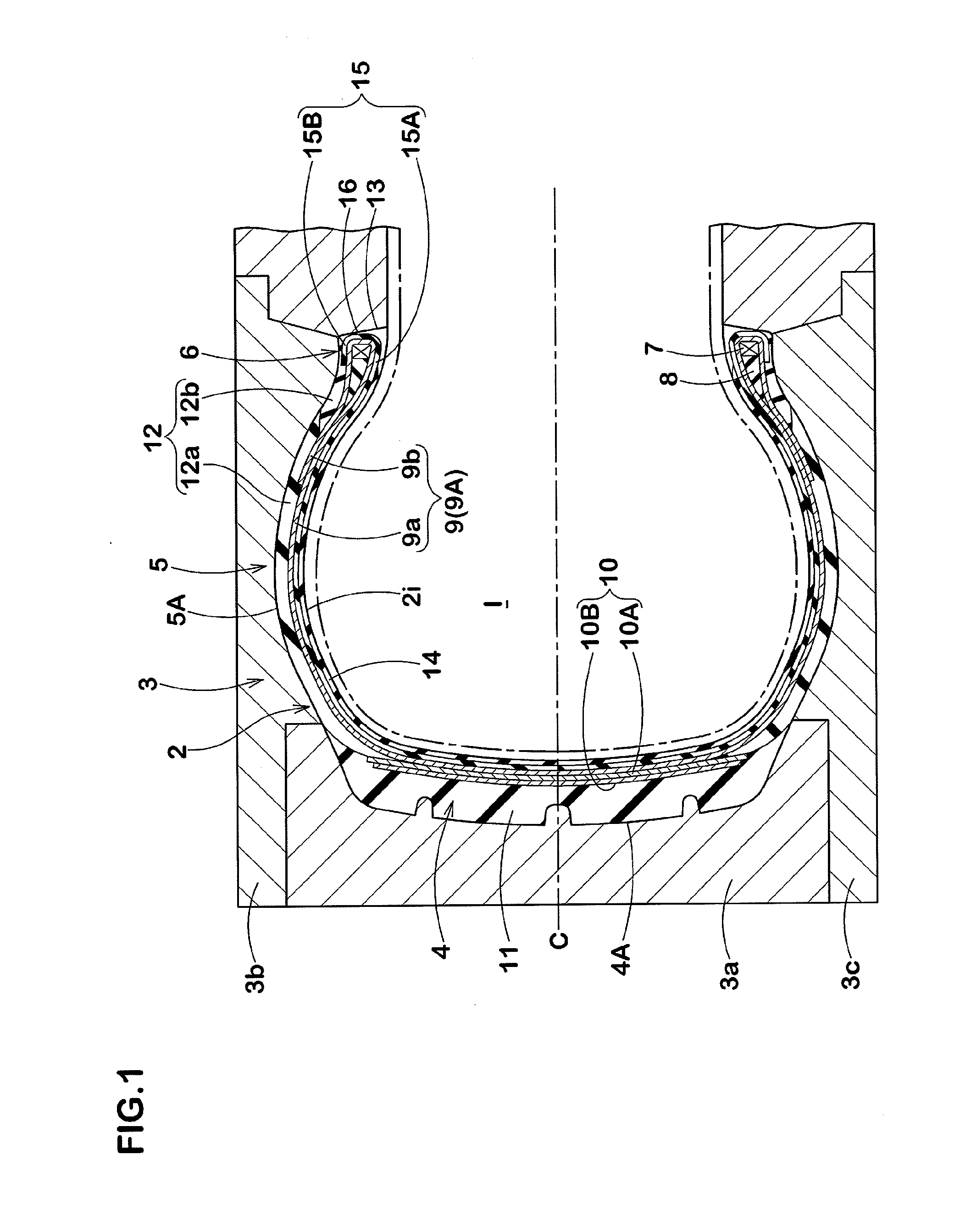
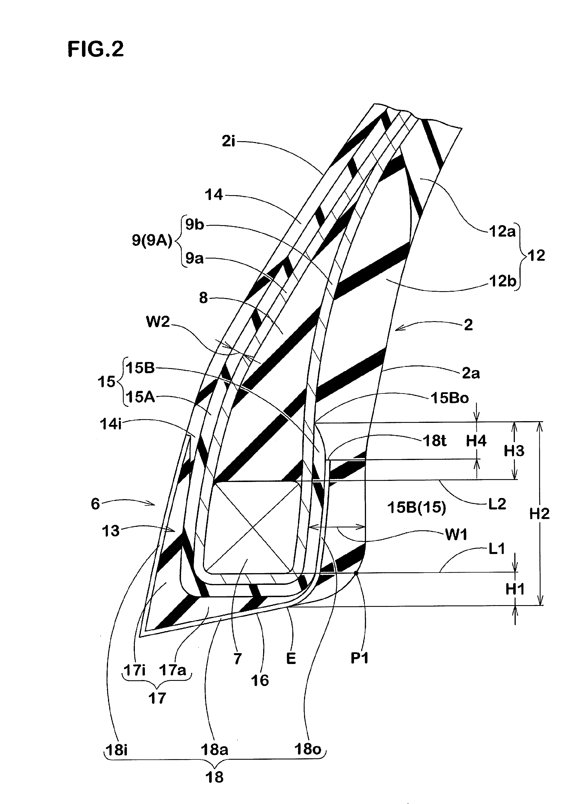
[0017]In such a manufacturing method for pneumatic tire, in an inserted state of the raw cover into the mold, a sidewall rubber edge, which is a boundary part between the above-mentioned sidewall rubber appearing on a surface of a raw cover outer surface and the bead chafer, is disposed more inward in the tire radial direction than a core inner point P1 where the raw cover outer surface intersects with a tire axial-directional line L1 passing through a radially inner edge of the above-mentioned bead core. Therefore, the sidewall edge is not forced by the large compressive force generated between the bead core and the mold during vulcanization; and the deformation of the sidewall rubber edge can be suppressed. Thus, the bare arising near the sidewall edge can be suppressed.
[0018]Moreover, the above-mentioned raw cover is provided with an insulation rubber comprising a main portion extending between the carcass and the inner liner from the tread portion through the sidewall portion to the bead portion, and a turn-up part connecting with this main portion and turned-up around the bead core form the axially inside to the axial outside of the tire. The outer edge of the turn-up part of the insulation rubber passes between a turn-up part of the carcass ply and the sidewall rubber and terminates more outward in the tire radial direction than the sidewall rubber edge. Therefore, the insulation rubber helps to increase a rubber thickness of the bead portion, and it can absorb the large compressive force generated between the bead core and the mold during vulcanization and can suppress a rigidity gap with the sidewall rubber edge. Therefore, the bare generation can be effectively suppressed.
[0019]Moreover, the insulation rubber has the adherence property superior to the inner liner and can joint with the carcass and the sidewall rubber solidly. Therefore, the joint strength with the carcass and the sidewall rubber can be sufficiently ensured, so that the durability of the bead portion is improved.

Problems solved by technology

However, this kind of pneumatic tire has a problem that a bare (b) is apt to arise on a tire surface of a bead portion (a) as shown in FIG. 4(a).
Furthermore, as the cause of a furtherance of the bare (b), it is also suggested that a compressional force during vulcanization cannot be sufficiently absorbed owing to reducing a thickness of the bead portion (a) because of omitting such a bead-reinforcing layer.

Method used


Image

  • Manufacturing method for pneumatic tire
  • Manufacturing method for pneumatic tire
  • Manufacturing method for pneumatic tire

Examples


embodiment

[0073]A raw cover (tire size: 195 / 65R15) having a basic structure shown in FIG. 1 and comprising a structure of a bead portion having a specification shown in Table 1 was formed; and a shape forming defection and the like during vulcanization was tested. Moreover, for comparison, the same tests were conducted with regard to a raw cover comprising a sidewall rubber edge disposed between a core outer point and a core inner point shown in FIG. 4(b) (comparative Example 1), and a raw cover comprising a sidewall rubber edge disposed more outward in the tire radial direction than the core outer point and an inner liner turned-up around a bead core as shown in FIG. 5 (comparative Example 2).

[0074]The test processes were as follows.

[0075]A thousand of each of the above-mentioned raw covers were formed in vulcanization by use of a mold, and a bare arising in a sidewall edge was checked up with the naked eye. Evaluation was made for a bare incidence; and the smaller the numeric values were, t...


PUM

PropertyMeasurementUnit
radial lengthaaaaaaaaaa
thicknessaaaaaaaaaa
angleaaaaaaaaaa

Abstract

A manufacturing method for pneumatic tire includes a process in which a raw cover (2) for a tire is formed, and a vulcanization process in which said raw cover (2) is inserted into a mold (3) and subjected to vulcanization molding. With the raw cover (2) inserted into the mold (3), a sidewall rubber edge (E), which is a boundary part between a bead chafer (13) and a sidewall rubber (12) that appears on an outer surface (2a) of the raw cover, is located further to the inside of the tire in the radial direction than an inner core point (P1), which is the intersection point between the outer surface (2a) of the raw cover and an axial line (L1) that passes through a bead core (7) on the inner edge of the tire in the radial direction.

Description

TECHNICAL FIELD[0001]The present invention relates to a manufacturing method for pneumatic tire capable of suppressing generation of a bare near a sidewall rubber edge while improving durability.BACKGROUND ART[0002]Recently, a pneumatic tire is known to have an improved noise-property and ride comfort owing to omitting a bead-reinforcing layer disposed separately from a carcass so as to reduce a rigidity of a bead portion. However, this kind of pneumatic tire has a problem that a bare (b) is apt to arise on a tire surface of a bead portion (a) as shown in FIG. 4(a). Also, the term “bare” is defined as a dent (defect) generated on the vulcanized tire surface because of a vulcanization of a raw cover of the tire by using a mold while keeping an air between the raw cover and the mold.[0003]The inventors of the present invention found that a sidewall rubber edge (e), which is the radially inner edge of a sidewall rubber (c), deforms under a pressure from a large compressional force betw...

Claims


Application Information

Patent Timeline
Patent Type & Authority Applications(United States)
IPC IPC(8): B29D30/08
CPCB29D30/1628B29D30/3028B29D30/32B60C2015/0617B29D2030/3292B60C2015/0614B29D30/72
Inventor ADACHI, YUKISHIGE
Owner SUMITOMO RUBBER IND LTD
Learn More