
Jaw strengthening device

a technology for strengthening devices and jaws, applied in the direction of muscle strengthening devices, gymnastic exercise, sport apparatus, etc., can solve the problems of devices not following affecting the natural movement of the jaw, and damage to the jaw of a person

Active Publication Date: 2012-11-08
MARTIN MICHAEL +1
View PDF3 Cites 23 Cited by
  • Summary
  • Abstract
  • Description
  • Claims
  • Application Information

AI Technical Summary

Benefits of technology

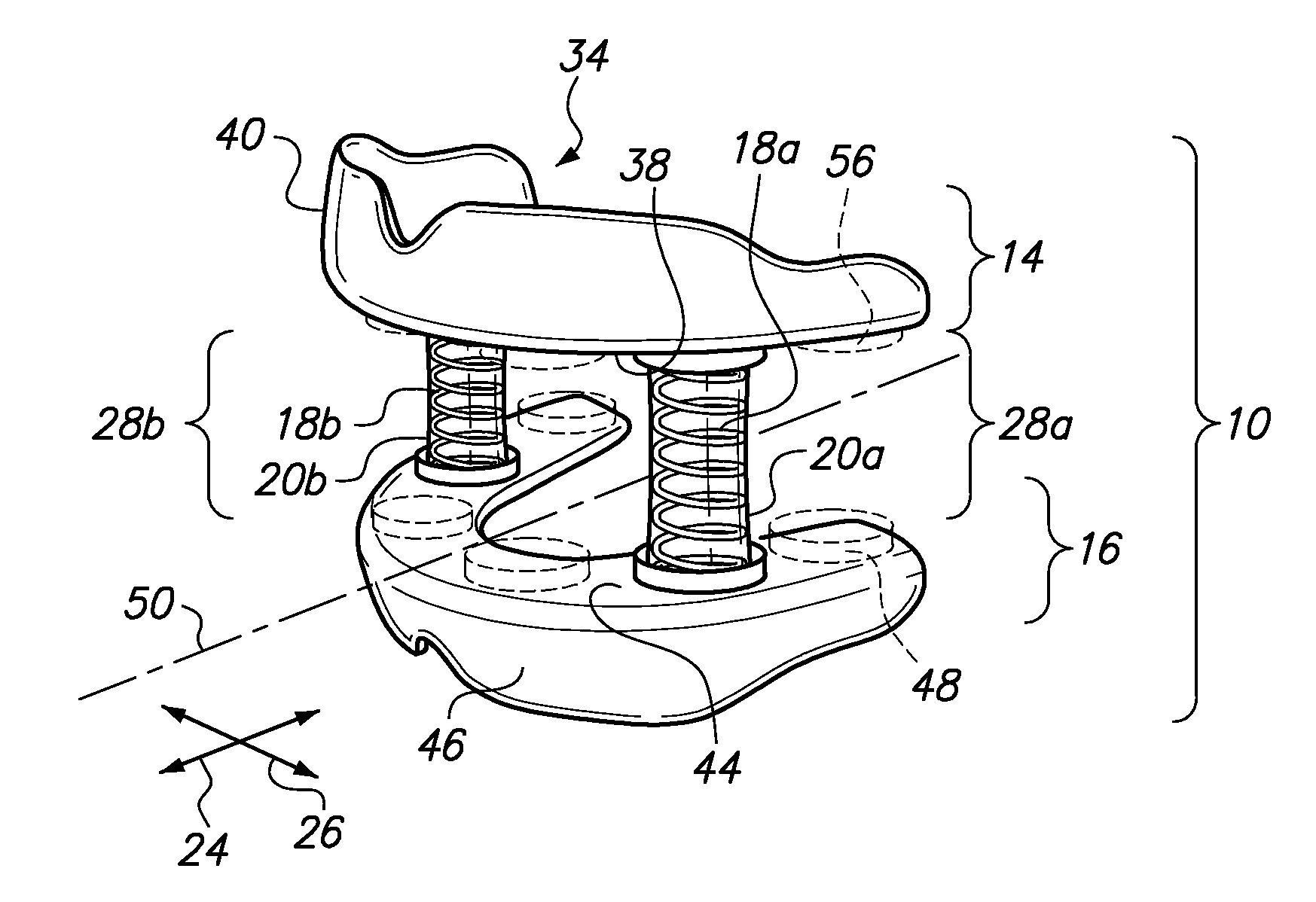
[0015]The spring may be a straight, cylindrically shaped compression spring allowing for lateral movement and front to back movement to allow the upper and lower mouthpieces to track natural movement of the jaw. The straight, cylindrically shaped compression spring may be the sole hinge between the upper and lower mouthpieces. The spring may alternatively be a tapered spring to allow for a greater stroke compared to the straight cylindrically shaped compression spring.
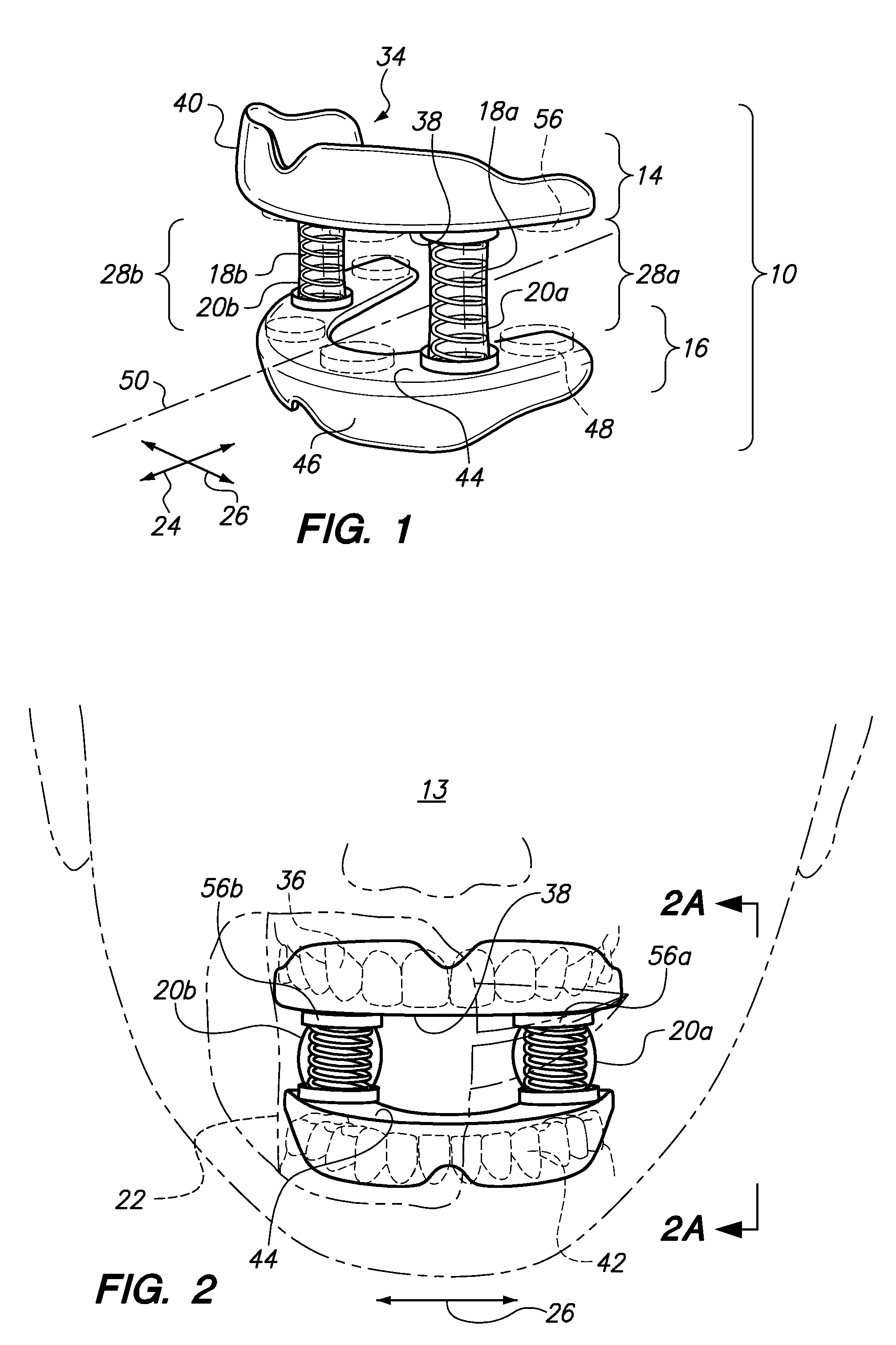
[0019]In another embodiment, a jaw strengthening device for rehabilitating one or more muscles associated with movement of a jaw is disclosed. The device may comprise an upper mouthpiece, a lower mouthpiece, a coil compression spring, and a flexible membrane. The upper mouthpiece may receive upper teeth of the jaw. The lower mouthpiece may receive lower teeth of the jaw. The coil compression spring may be disposed between the upper and lower mouthpieces. An upper end of the spring may be attached to the upper mouthpiece. A lower end of the spring may be attached to the lower mouthpiece to exercise the muscles associated with the jaw by biting down and loading the spring. The flexible membrane may be wrapped around the compression coil spring. The flexible membrane may expand outwardly during a compression stroke of the spring to prevent an inside of a cheek from being pinched between coils of the spring.

Problems solved by technology

Accidents may cause damage to a person's jaw.
These accidents may occur during sports play, automobile accidents, etc.
Unfortunately, current devices for rehabilitating the jaw have certain deficiencies.
In particular, prior art devices typically have upper and lower mouthpieces that are spring loaded.
Unfortunately, these devices do not follow the natural movement of the jaw which may be non-circular and non-linear.
Rather, the jaw movement of a person may be quite complex with forward to back movement and side to side movement.
These devices also extend out of the person's mouth and are aesthetically obtrusion or displeasing to look at.

Method used


Image

  • Jaw strengthening device
  • Jaw strengthening device
  • Jaw strengthening device

Examples


Embodiment Construction

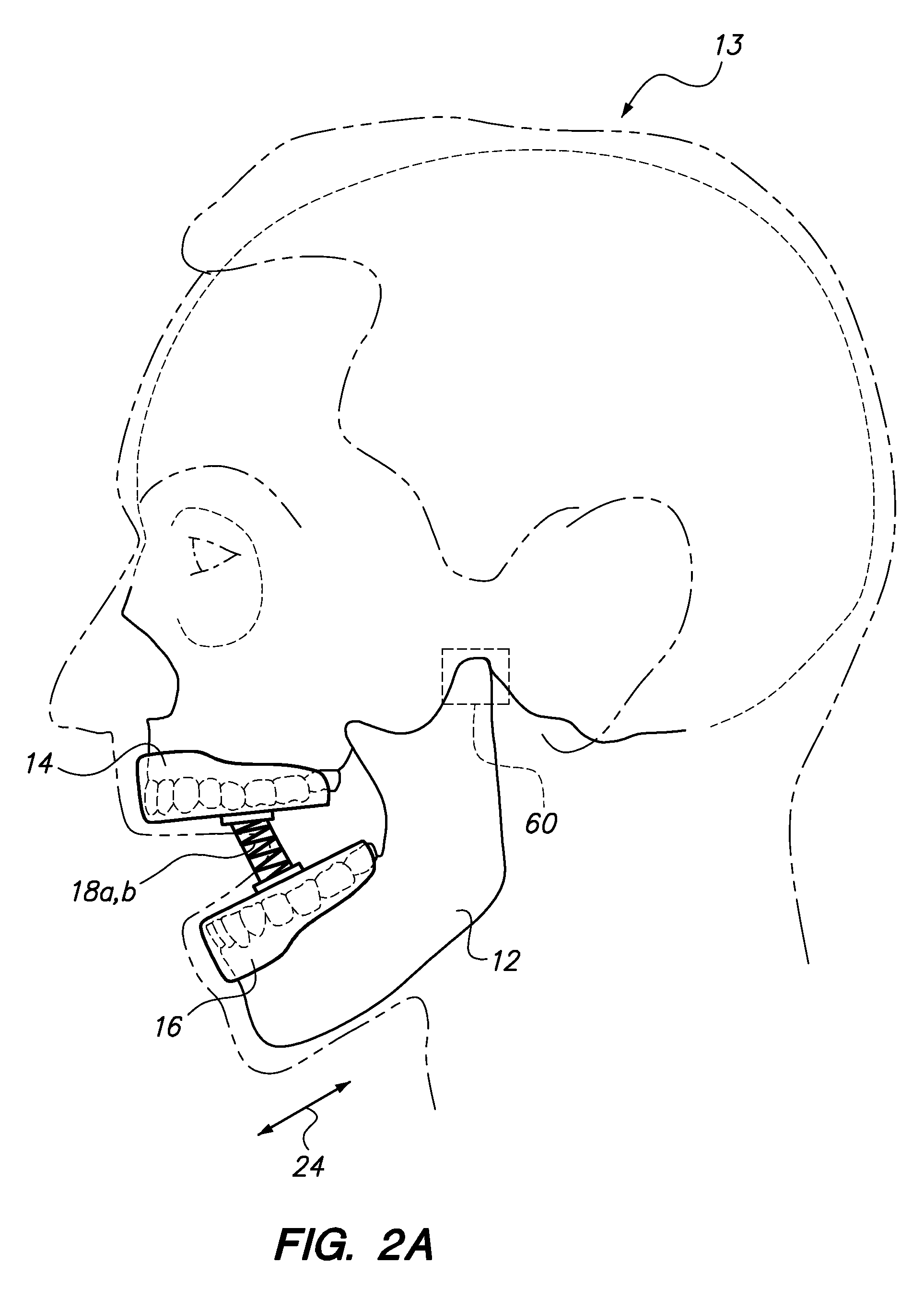
[0031]Referring now to the drawings, a jaw strengthening device 10 is shown. The jaw strengthening device 10 is used for the purpose of rehabilitating one or more muscles associated with the movement of a jaw 12 (see FIG. 2A) of a person 13. The device 10 may have an upper mouth piece 14 and a lower mouth piece 16 that are held together by springs 18a, b. The springs 18a, b may each be disposed within a flexible tube 20a, b that expands outwardly as shown in FIG. 2, to prevent a cheek 22 of a person 13 from being pinched between the coils of the springs 18a, b. Moreover, the upper and lower mouthpieces 14, 16 are not hinged together and not rotated about a fixed pivot point so that the upper and lower mouthpieces 14, 16 may track the natural movement of the jaw 12 as the muscles of the jaw 12 are exercised by opening and biting down on the upper and lower mouth pieces 14, 16. The coil springs 18a, b allow front to back motion of the mouth pieces 14, 16 in the direction of arrow 24 s...


PUM


Abstract

A jaw strengthening device may have an upper mouthpiece and a lower mouthpiece. These mouthpieces may be attached to each other by way of a coil compression spring. This allows the upper and lower mouthpieces to shift front and back as well as laterally so that the upper and lower mouthpieces do not track a specific pivot point, but can follow the natural movement of the jaw. A film is wrapped around the spring and expands outwardly as the user bites down on the mouthpieces to push the inside surface of the person's cheek away from the coils of the spring and prevent the coils of the spring from pinching the user's cheek. Additionally, the device may be inserted inside the person's mouth so that the device is not aesthetically obtrusive.

Description

CROSS-REFERENCE TO RELATED APPLICATIONS[0001]Not ApplicableSTATEMENT RE: FEDERALLY SPONSORED RESEARCH / DEVELOPMENT[0002]Not ApplicableBACKGROUND[0003]The embodiments disclosed herein relate to a device for strengthening muscles associated with a person's jaw.[0004]Accidents may cause damage to a person's jaw. These accidents may occur during sports play, automobile accidents, etc. For example, a mixed martial art fighter may be punched or kicked in the jaw which could shatter the person's jaw. In this event, surgery and extensive physical therapy may be necessary in order to rehabilitate the jaw and the muscles associated with the jaw. Unfortunately, current devices for rehabilitating the jaw have certain deficiencies.[0005]In particular, prior art devices typically have upper and lower mouthpieces that are spring loaded. The upper and lower mouth pieces of these devices have a defined path of travel. The defined path of travel may be an arc about a fixed pivot point or linear within...

Claims


Application Information

Patent Timeline
Patent Type & Authority Applications(United States)
IPC IPC(8): A63B23/03
CPCA63B23/032A63B21/023
Inventor MARTIN, MICHAELMARTIN, GREGORY
Owner MARTIN MICHAEL
Learn More