
Lightning protection system for a wind turbine, wind turbine and method for protecting components of a wind turbine against lightning strikes

Active Publication Date: 2012-11-08
SIEMENS GAMESA RENEWABLE ENERGY AS
View PDF6 Cites 14 Cited by
  • Summary
  • Abstract
  • Description
  • Claims
  • Application Information

AI Technical Summary

Benefits of technology

[0007]An improved lightning protection system for a wind turbine is provided. Further, a wind turbine, which overcomes the previously mentioned difficulties and reduces the mentioned risks, is provided. Also, a method for protecting components of a wind turbine against lightning strikes is provided, which reduces the risk that electrical current from a lightning strike jumps from the lightning conducting path to a component close to the lightning conducting path and then further to the generator.

Problems solved by technology

The combination of a high voltage, large electrical current and strong resulting electromagnetic fields from the lightning strike could damage the generator or other electrical components of the wind turbine.
Having a direct drive wind turbine, also called a gearless wind turbine, makes it is more difficult to conduct the lightning strike from one or more of the blades through the wind turbine without damaging especially the generator as it is connected directly to the blade hub of the wind turbine.
Having a direct drive wind turbine with a generator with an outer rotating rotor makes it even more difficult to find a way to conduct the electrical current from the lightning strike on the blades of the wind turbine to the ground without damaging the generator.
This kind of lightning protection system does not work for a direct drive wind turbine where the generator is connected directly to the hub as the generator then might be damaged by a lightning strike.
The lightning conducting path around a hub is quite long with one or more directional shifts or turns and every place where this path has a directional shift or turn there is a substantial risk that the electrical current from the lightning strike jumps from the lightning conducting path to a component close to the lightning conducting path, like e.g. the blade hub and then further to the generator.

Method used


Image

  • Lightning protection system for a wind turbine, wind turbine and method for protecting components of a wind turbine against lightning strikes
  • Lightning protection system for a wind turbine, wind turbine and method for protecting components of a wind turbine against lightning strikes
  • Lightning protection system for a wind turbine, wind turbine and method for protecting components of a wind turbine against lightning strikes

Examples


Embodiment Construction

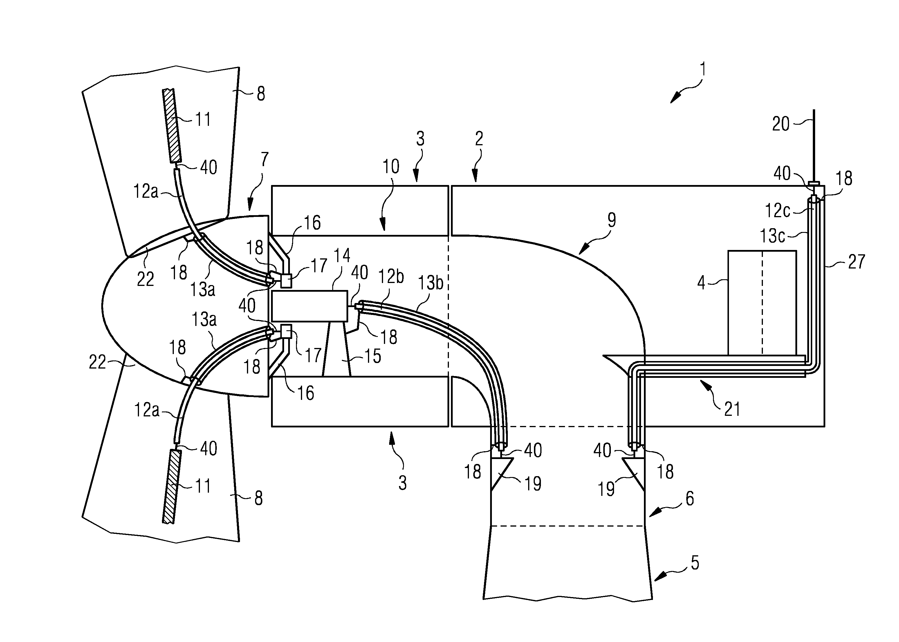
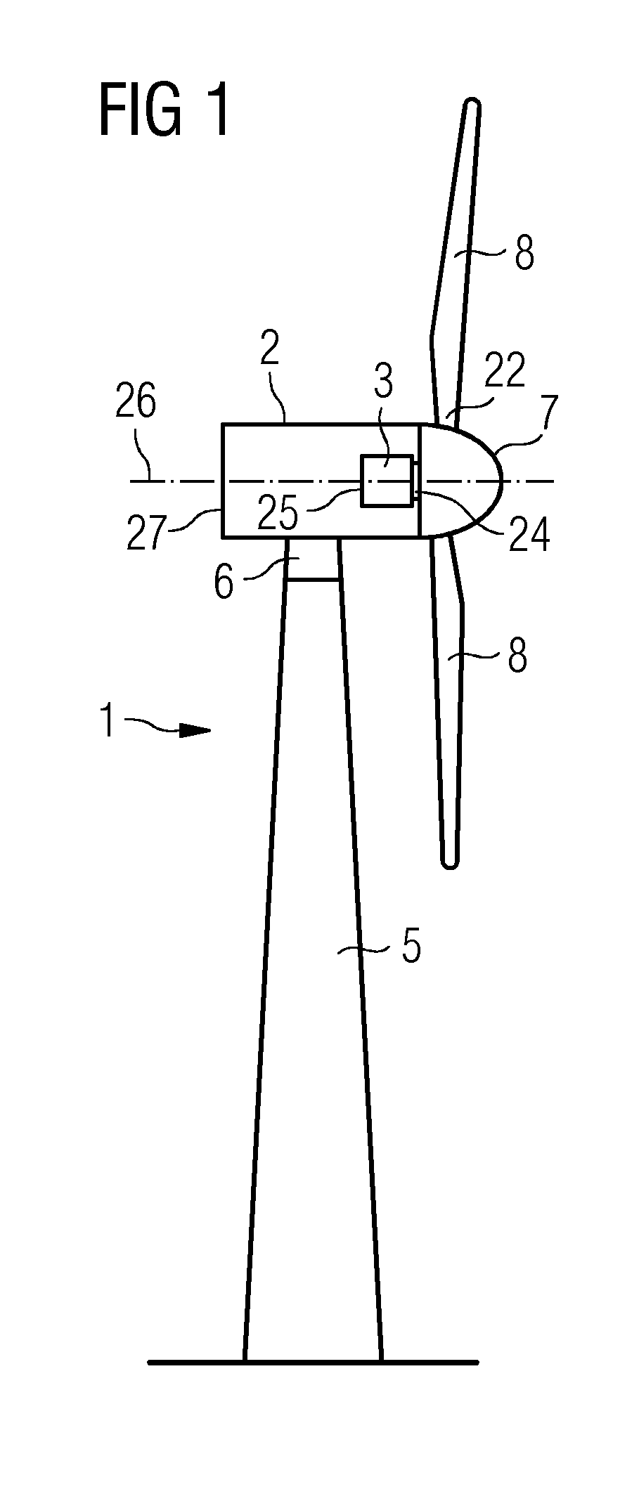
[0034]FIG. 1 schematically shows a wind turbine 1. The wind turbine 1 comprises a tower 5, a nacelle 2 and a hub 7. The nacelle 2 is located on top of the tower 5. A transition piece 6 is located between the tower 5 and the nacelle 2. The hub 7 comprises a number of wind turbine blades 8. The hub 7 is mounted to the nacelle 2. Moreover, the hub 7 is pivot-mounted such that it is able to rotate about a rotation axis 26. The nacelle 2 comprises a far side 27, which is located opposite to the hub 7.

[0035]A generator 3 is located inside the nacelle 2. The generator 3 comprises a near side 24 facing the hub 7 and a far side 25 opposite to the hub 7. Generally, the generator 3 may have an outer rotor configuration or an inner rotor configuration. The wind turbine 1 is a direct drive wind turbine.

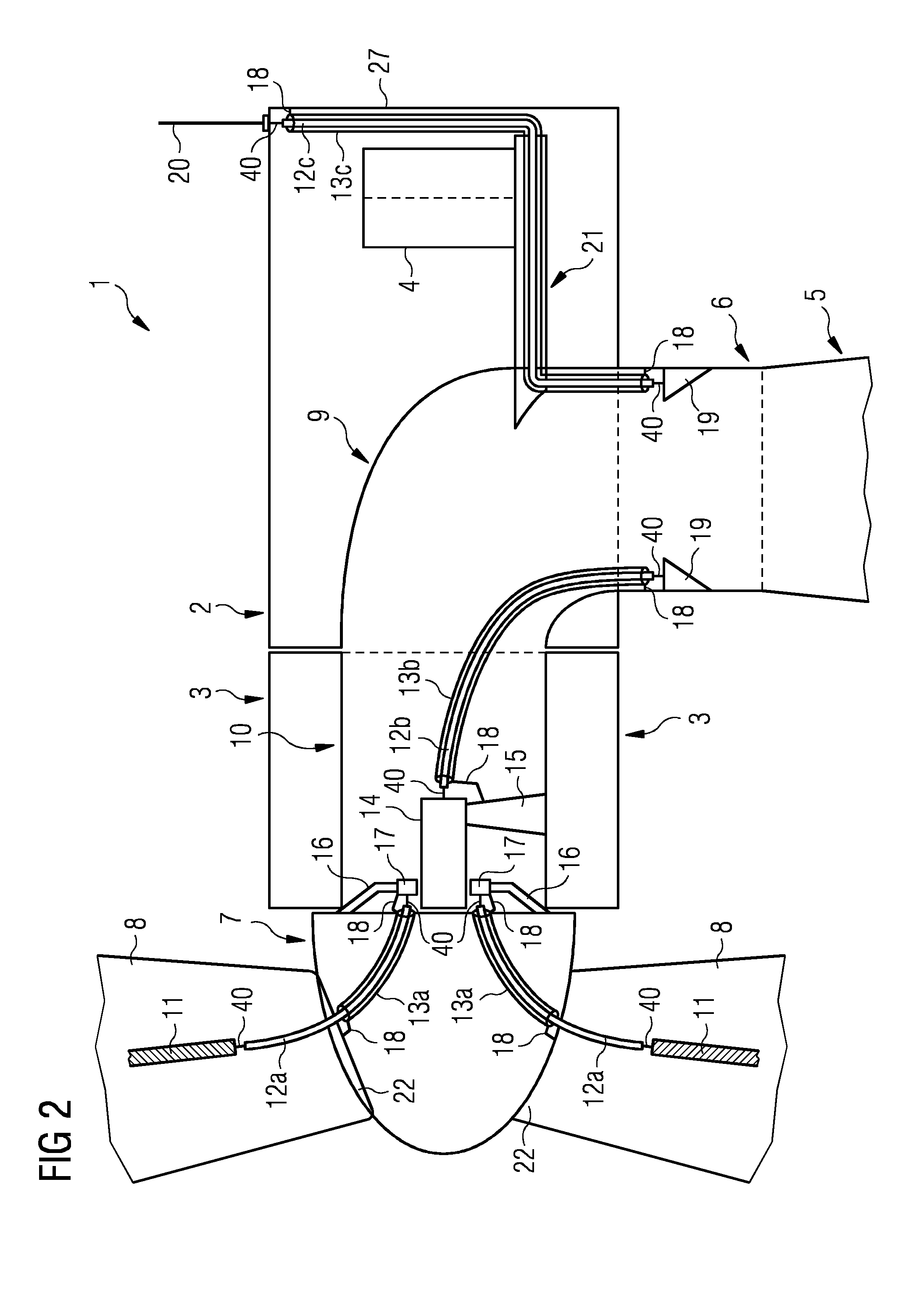
[0036]FIG. 2 schematically shows part of the wind turbine 1. The wind turbine 1 comprises a direct-drive generator 3 which is located between the nacelle 2 and the hub 7. Alternatively, the direct...


PUM

PropertyMeasurementUnit
Electric potential / voltageaaaaaaaaaa

Abstract

A lightning protection system for a wind turbine includes at least one insulated high-voltage cable, a pick-up unit and an additional insulated high-voltage cable. The at least one insulated high-voltage cable is electrically connected to a lightning receptor and to the pick-up unit. The pick-up unit is electrically connectable to an electrically grounded member by the additional insulated high-voltage cable.

Description

CROSS REFERENCE TO RELATED APPLICATIONS[0001]This application claims priority of European Patent Office Application No. 11164586.7 EP filed May 3, 2011. All of the applications are incorporated by reference herein in their entirety.FIELD OF INVENTION[0002]A lightning protection system for a wind turbine is provided. Further, a wind turbine and a method for protecting components, for example electrical components, of a wind turbine against lightning strikes are provided.BACKGROUND OF INVENTION[0003]When a lightning strikes a wind turbine, the lightning often hits an area of one or more of the blades from where the current from the lightning strike is conducted inside or outside the blade by conducting means, like a down conductor, to one or more wind turbine components like the hub, the nacelle and the tower and further down to the ground. The aim is though to ensure that the current from the lightning strike on its way through the wind turbine does not reach any electrical component...

Claims


Application Information

Patent Timeline
IPC IPC(8): F03D11/00H02H3/22H01R43/00
CPCF03D11/00F03D11/0033Y10T29/49117Y02E10/722Y02E10/725F05B2220/7066F03D80/00F03D80/30Y02E10/72F03D1/0633F03D1/0691H02G13/00H05F3/02
Inventor LEWKE, BASTIANOLSEN, KAJ
Owner SIEMENS GAMESA RENEWABLE ENERGY AS
Learn More