
Wireless array device and system for managing wireless arrays having magnetometers

a wireless array and magnetometer technology, applied in the field of wireless communication devices, can solve problems such as poor wireless communication, interference and performance degradation, and prone to errors

Active Publication Date: 2012-11-01
CAMBIUM NETWORKS
View PDF5 Cites 32 Cited by
  • Summary
  • Abstract
  • Description
  • Claims
  • Application Information

AI Technical Summary

Benefits of technology

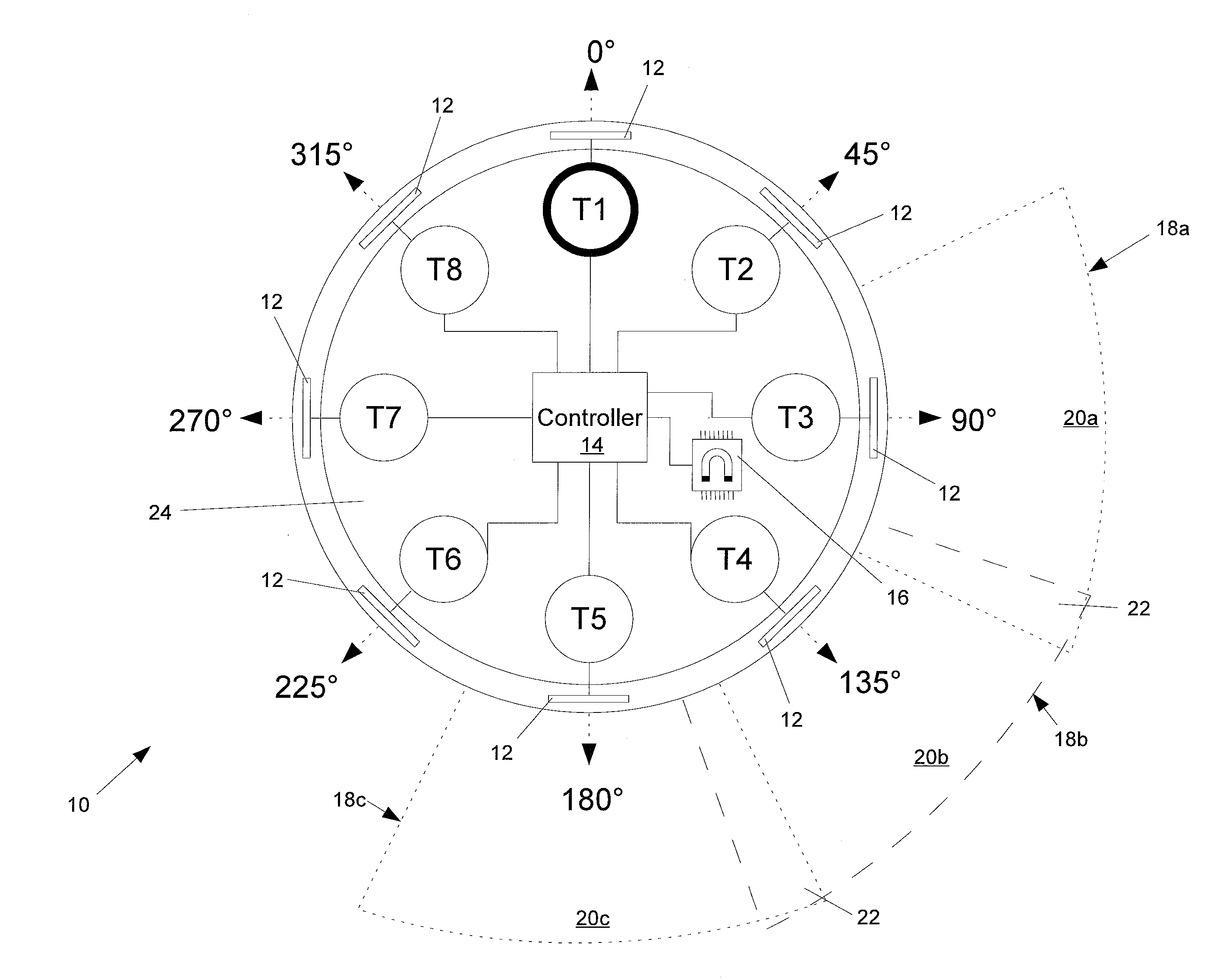
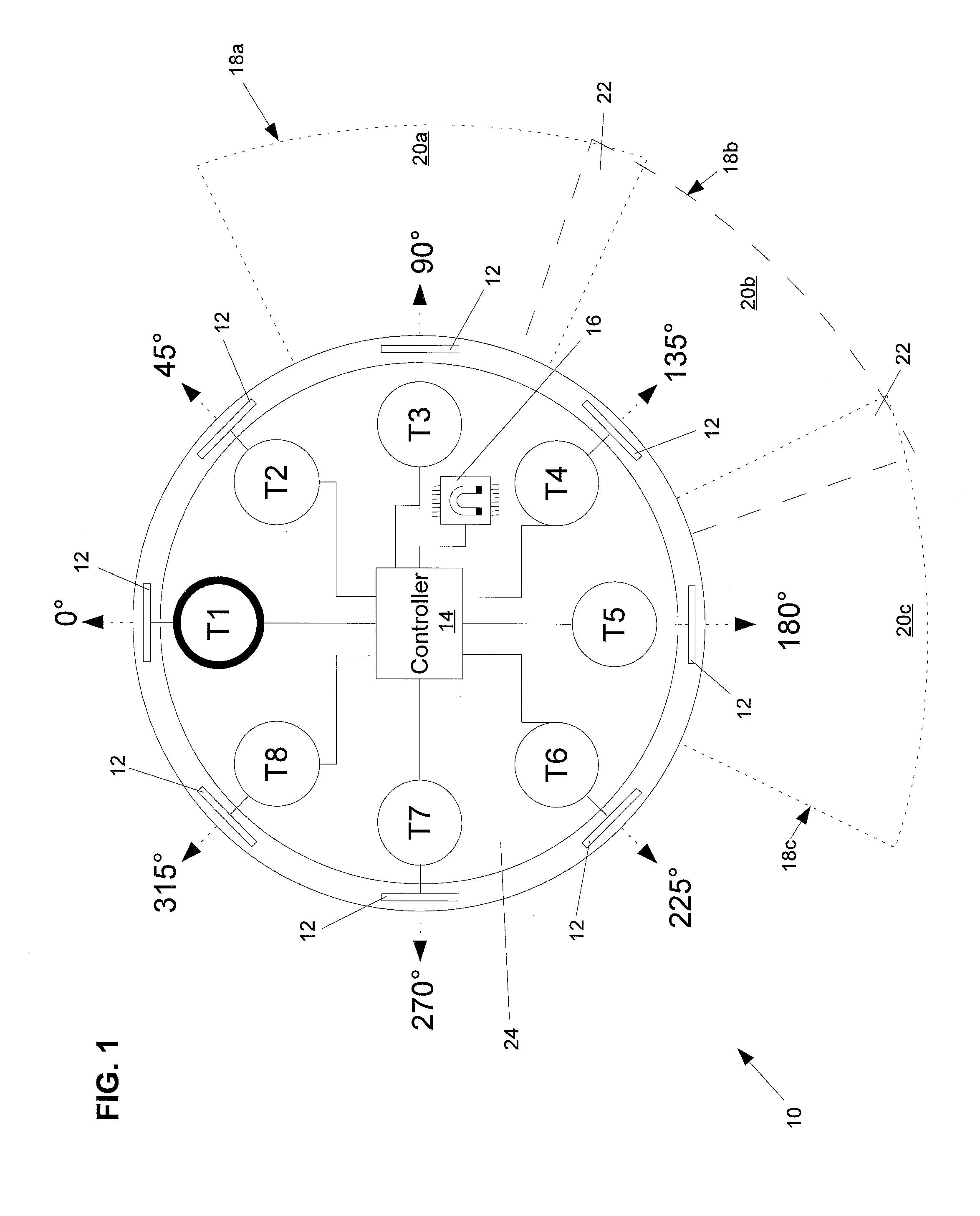
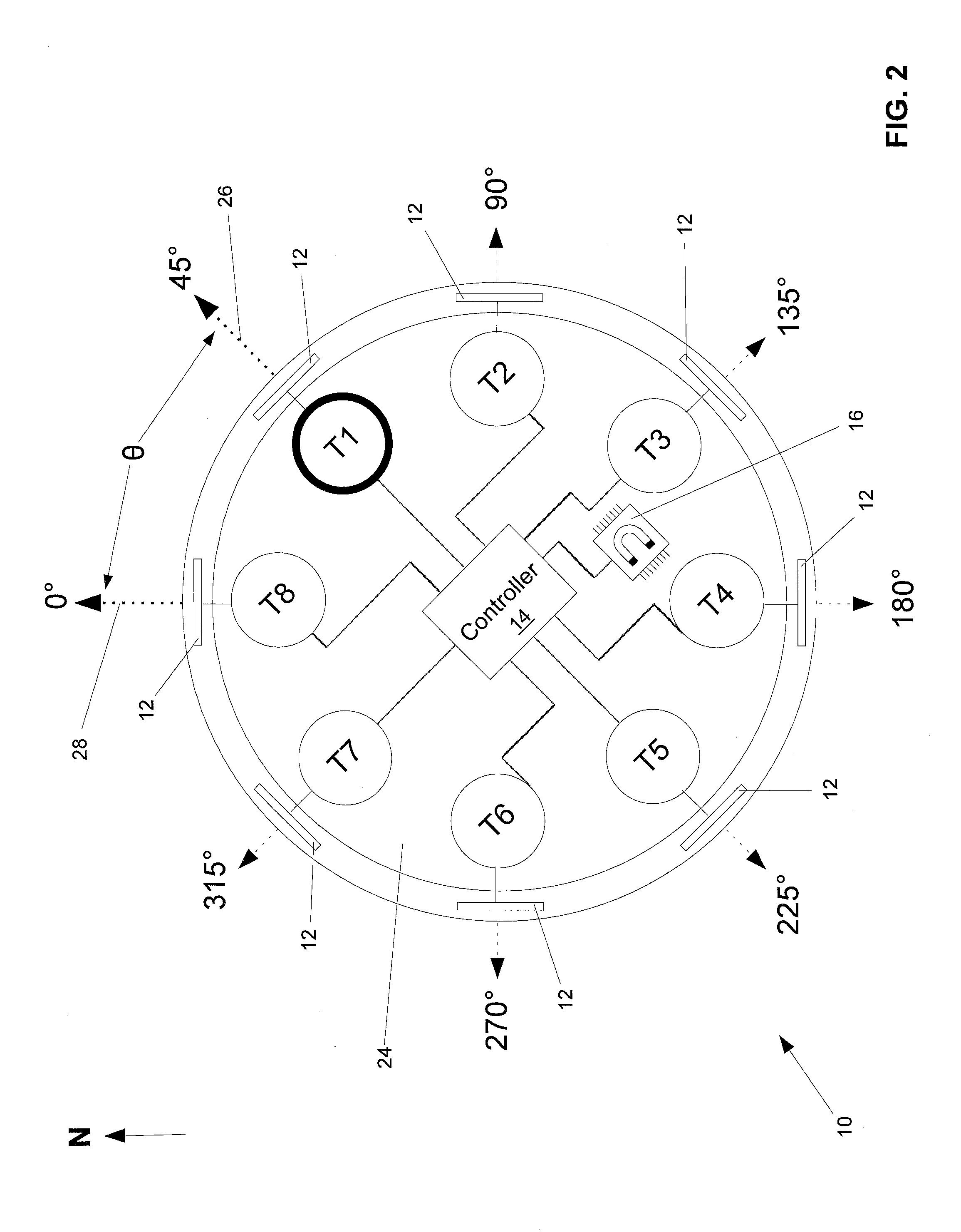
[0011]A wireless array that provides access to a network is shown. The wireless array includes at least two transceivers in signal communication with one or more clients. A magnetometer of the wireless array provides orientation information relating to the orientation of the wireless array relative to a magnetic field. A controller of the wireless array is in signal communication with the transceivers and the magnetometer. The controller manages the communications exchanged via the transceivers and receives the orientation information provided by the magnetometer.
[0012]A system that manages wireless arrays deployed in a network is also provided. The system includes at least two wireless arrays deployed

Problems solved by technology

Overlapping frequencies may degrade performance and result in poor wireless communications due to, for example, low throughput.
However, overlapping frequencies may also result when multiple wireless access devices are installed in various locations around the campuses of businesses, hospitals, schools, and the like to provide campus-wide wireless coverage.
If the antenna patterns of the radios operating at the same frequency overlap, interference and performance degradation may result as discussed above.
However, existing methods to acquire orientation information may rely on visual inspection and estimation.
These conventional methods may be prone to error and lead to misleading or inaccurate information regarding the orientation of a wireless access device.

Method used


Image

  • Wireless array device and system for managing wireless arrays having magnetometers
  • Wireless array device and system for managing wireless arrays having magnetometers
  • Wireless array device and system for managing wireless arrays having magnetometers

Examples


Embodiment Construction

[0020]A wireless array device and system for managing wireless arrays having magnetometers is described in this application. Referring to FIG. 1, an example wireless access device 10 that provides orientation information is shown. The wireless access device 10 includes multiple transceivers T1-T8, which may be used to provide a client with wireless access to a network by exchanging wireless communications with the client. The wireless access device may be described as being in signal communication with the client, in particular in signal communication with the client.

[0021]The term “in signal communication” as used in the application means that two or more devices and / or components are capable of communicating with each other via signals that travel over some type of signal path. Signal communication may be wired or wireless. The signals may be communication, power, data, or energy signals which may communicate information, power, and / or energy from a first device and / or component t...


PUM


Abstract

A wireless array for providing access to a network is provided. The wireless array includes at least two transceivers in signal communication with a client. A magnetometer of the wireless array provides orientation information relating to an orientation of the wireless array relative to a magnetic field. A controller of the wireless array is in signal communication with the transceivers and the magnetometer. The controller manages the communications exchanged via the transceivers and receives the orientation information provided by the magnetometer.

Description

CROSS-REFERENCE TO RELATED APPLICATION[0001]This application is a continuation-in-part of U.S. patent application Ser. No. 13 / 094,049 titled METHOD FOR DETERMINING A GEOSPATIAL LOCATION OF A CLIENT IN SIGNAL COMMUNICATION WITH A WIRELESS ARRAY, filed on Apr. 26, 2011, which is incorporated by reference in its entirety in this application.BACKGROUND[0002]1. Field of the Invention[0003]This invention relates to wireless communication devices and more particularly to wireless communication devices that provide information relating to the alignment and orientation of the device.[0004]2. Description of Related Art[0005]The use of wireless communication devices for data networking continues to grow at a rapid pace. Data networks that use “WiFi” (“Wireless Fidelity”), also known as “Wi-Fi,” are relatively easy to install, convenient to use, and supported by the IEEE 802.11 standard. WiFi data networks also provide performance that makes WiFi a suitable alternative to a wired data network f...

Claims


Application Information

Patent Timeline
IPC IPC(8): H04W4/00
CPCH01Q1/007H01Q9/285H01Q19/106H01Q21/205G01R33/0094H04W88/06H04W64/00H04W72/046H04W4/023H04W4/026H04W72/0453H04W16/28
Inventor KRATTIGER, STEVENHAND, ALANHARTENSTEIN, ABRAHAM
Owner CAMBIUM NETWORKS
Learn More