Band-pass filter
a filter and band-pass technology, applied in the direction of waveguide devices, basic electric elements, electrical equipment, etc., can solve problems such as interference with the received rf signal
- Summary
- Abstract
- Description
- Claims
- Application Information
AI Technical Summary
Problems solved by technology
Method used
Image
Examples
Embodiment Construction
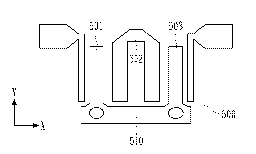
[0021]FIG. 5 shows a band-pass filter structure according to an embodiment of the present invention. As shown in FIG. 5, the band-pass filter 500 comprises a first resonator 501, a second resonator 502 and a third resonator 503. The first resonator 501, the second resonator 502 and the third resonator 503 are arranged along the X-direction with the second resonator 502 sandwiched between the first resonator 501 and the third resonator 503. The first resonator 501 and the third resonator 503 are both quarter wavelength resonators. That is, the lengths of the first resonator 501 and the third resonator 503 are a quarter of the wavelength of the electromagnetic wave received by the band-pass filter 500. In addition, both the first resonator 501 and the third resonator 503 are in a long strip shape extending along the Y-direction. Further, both the first resonator 501 and the third resonator 503 have one end connected to a ground line 510. The second resonator 502 is a half wavelength r...
PUM
 Abstract
Description
Claims
Application Information
 - R&D
- Intellectual Property
- Life Sciences
- Materials
- Tech Scout
- Unparalleled Data Quality
- Higher Quality Content
- 60% Fewer Hallucinations
Browse by: Latest US Patents, China's latest patents, Technical Efficacy Thesaurus, Application Domain, Technology Topic, Popular Technical Reports.
© 2025 PatSnap. All rights reserved.Legal|Privacy policy|Modern Slavery Act Transparency Statement|Sitemap|About US| Contact US: help@patsnap.com


