Vehicle body lower structure
a technology for lowering structures and vehicles, applied in vehicle arrangements, roofs, transportation and packaging, etc., can solve problems such as the difficulty of opening doors b>800/b>
- Summary
- Abstract
- Description
- Claims
- Application Information
AI Technical Summary
Benefits of technology
Problems solved by technology
Method used
Image
Examples
first modification
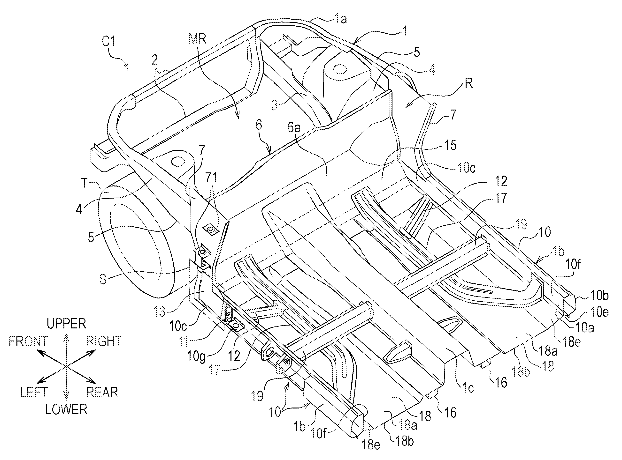
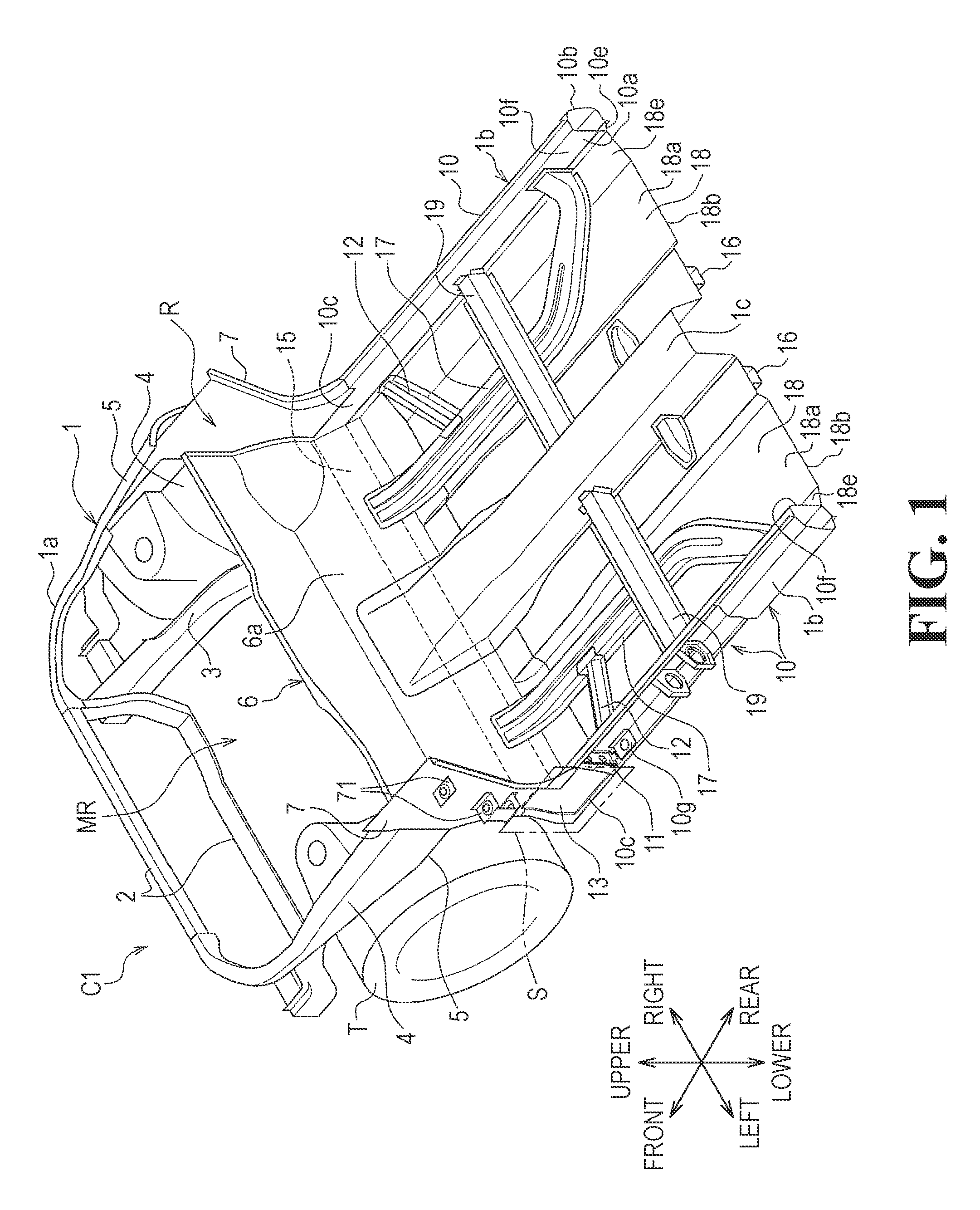
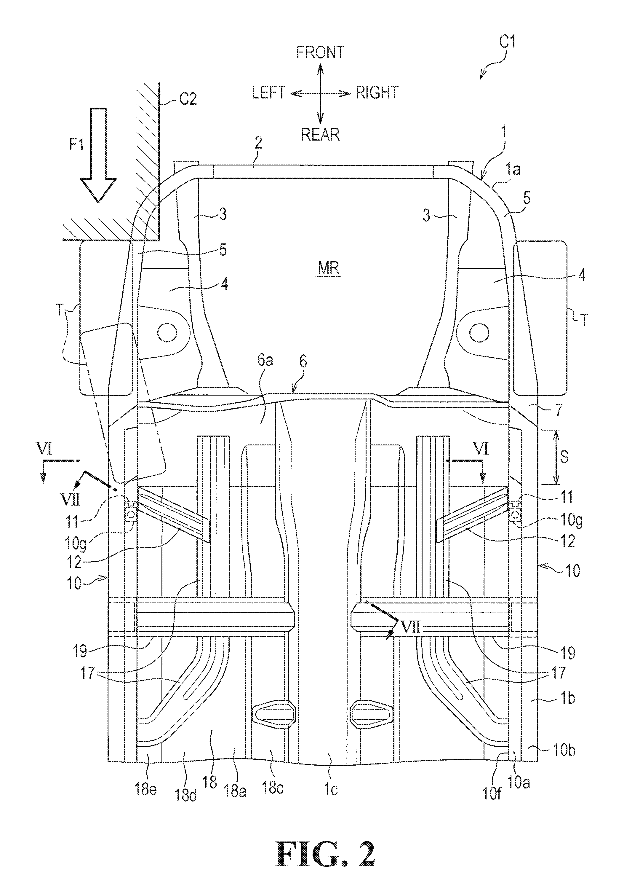
[0088]In the foregoing embodiment, each reinforcing frame 12 is disposed such that the inner joint 12g is joined to the upper surface of the floor frame 17, the outer joint 12f is joined to the outer end 18f of the floor panel 18 and the side surface 10f of the side sill 10 closer to the vehicle interior R, and the load transfer portion 12a (edge line 12d) is positioned below the cross-sectional centroid O1 of the side sill 10 as illustrated in FIG. 5. The placement is not limited to the above one.
[0089]For example, a reinforcing frame 12A may be disposed such that an approximate extension O2 of a load transfer portion 12Aa (edge line 12Ad) extends so as to pass through the cross-sectional centroid O1 of the side sill 10 as illustrated in FIG. 9A.
[0090]In this case, as illustrated in FIG. 9A, the reinforcing frame 12A is shaped such that the load transfer portion 12Aa (edge line 12Ad) of the reinforcing frame 12A is higher than the load transfer portion 12a (edge line 12d) of the re...
second modification
[0094]While the foregoing embodiment has been described with respect to the case where the outer end 18f of each floor panel 18 is joined to the side surface 10f of the corresponding side sill 10 closer to the vehicle interior R as illustrated in FIG. 5, the placement is not limited to the above one.
[0095]A floor panel 18B may be joined to a lower surface 10e of the side sill 10 as illustrated in FIG. 9B. In this placement, the height, indicated at H2, of a reinforcing frame 12B between each flange 12Be near an outer joint 12Bf and an edge line 12Bd is increased, so that the cross-sectional area of the reinforcing frame 12B can be increased with increase in height. Thus, the increased strength can be provided.
[0096]Furthermore, the reinforcing frame 12B may be formed horizontally as illustrated in FIG. 9B. In this case, the outer joint 12Bf of the reinforcing frame 12B is joined to the side surface 10f of the side sill 10 closer to the vehicle interior R and an inner joint 12Bg ther...
third modification
[0097]A reinforcing frame 12C and a floor frame 17C may be arranged below a floor surface 18Ca of each floor panel 18C as illustrated in FIG. 9C. In this arrangement, since the floor panel 18C may be formed flat, the floor surface 18Ca can be flattened.
[0098]In this case, the floor frame 17C is joined to the floor panel 18C such that flanges 17Cb and 17Cc are placed on the upper side. The upper surface of each flange 12Ce of the reinforcing frame 12C is joined to the floor frame 17C and an outer joint 12Cf thereof is joined to the lower surface 10e of the side sill 10.
Another modification
[0099]While the foregoing embodiment has been described with respect to the case where the components are made of steel, a high stiffness material may be used. The components may be made of light alloy, such as aluminum material (aluminum alloy), or resin material.
PUM
 Abstract
Description
Claims
Application Information
 - R&D
- Intellectual Property
- Life Sciences
- Materials
- Tech Scout
- Unparalleled Data Quality
- Higher Quality Content
- 60% Fewer Hallucinations
Browse by: Latest US Patents, China's latest patents, Technical Efficacy Thesaurus, Application Domain, Technology Topic, Popular Technical Reports.
© 2025 PatSnap. All rights reserved.Legal|Privacy policy|Modern Slavery Act Transparency Statement|Sitemap|About US| Contact US: help@patsnap.com


