
Adaptively Balanced Detector

a detector and balanced technology, applied in the field of adaptable balanced detectors, can solve the problems of detector imbalance, inability to achieve balanced detection, and increase the amount of interference caused by detector imbalan

Active Publication Date: 2012-10-04
INFINERA CORP
View PDF1 Cites 13 Cited by
  • Summary
  • Abstract
  • Description
  • Claims
  • Application Information

AI Technical Summary

Benefits of technology

[0010]Consistent with an additional aspect of the present disclosure, an apparatus is provided that includes an optical coupler having an input and first and second outputs, the input receiving a wavelength division multiplexed (WDM) optical signal. The WDM optical signal includes a plurality of optical channels each having a corresponding one of a plurality of wavelengths. The first output supplies a first portion of the WDM optical signal and the second output supplies a second portion of the WDM optical signal. The first photodiode is configured to receive the first portion of the WDM optical signal and supply a first electrical signal. An optical hybrid circuit is provided that is configured to receive at least a part of the second portion of the WDM optical signal. In addition, a laser is provided that is configured to supply a local oscillator optical signal to the optical hybrid circuit, such that the optical hybrid opti

Problems solved by technology

Typically, however, due to non-idealities associated with the photodiodes, the optical hybrid circuit, and / or other components, such balanced detection may not be achieved.
In other words, detection is “imbalanced”.
Detector imbalance can increase the amount of interference due to the presence of other signals in the superchannel being supplied to the photodiodes.

Method used


Image

  • Adaptively Balanced Detector
  • Adaptively Balanced Detector
  • Adaptively Balanced Detector

Examples


Embodiment Construction

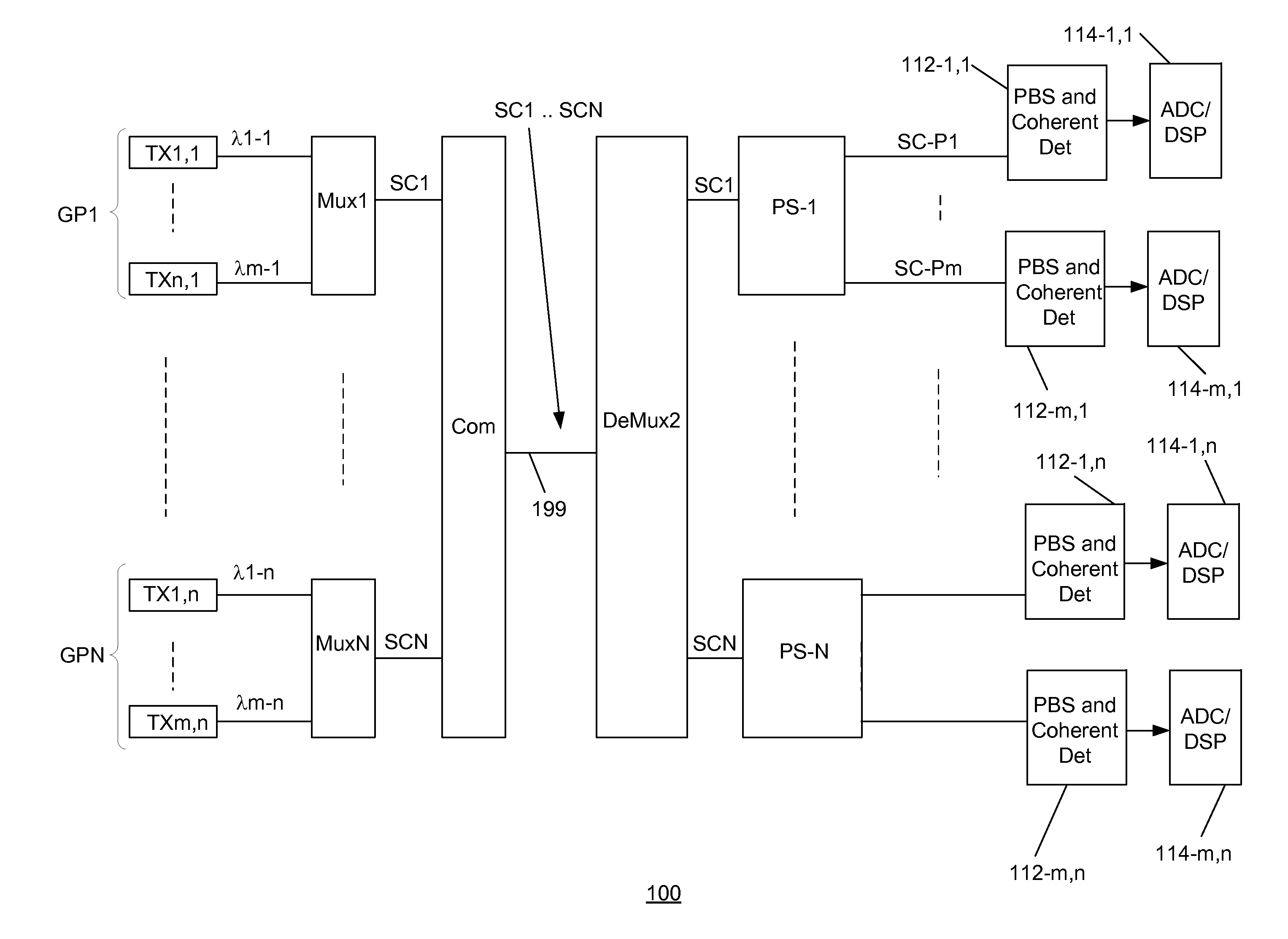
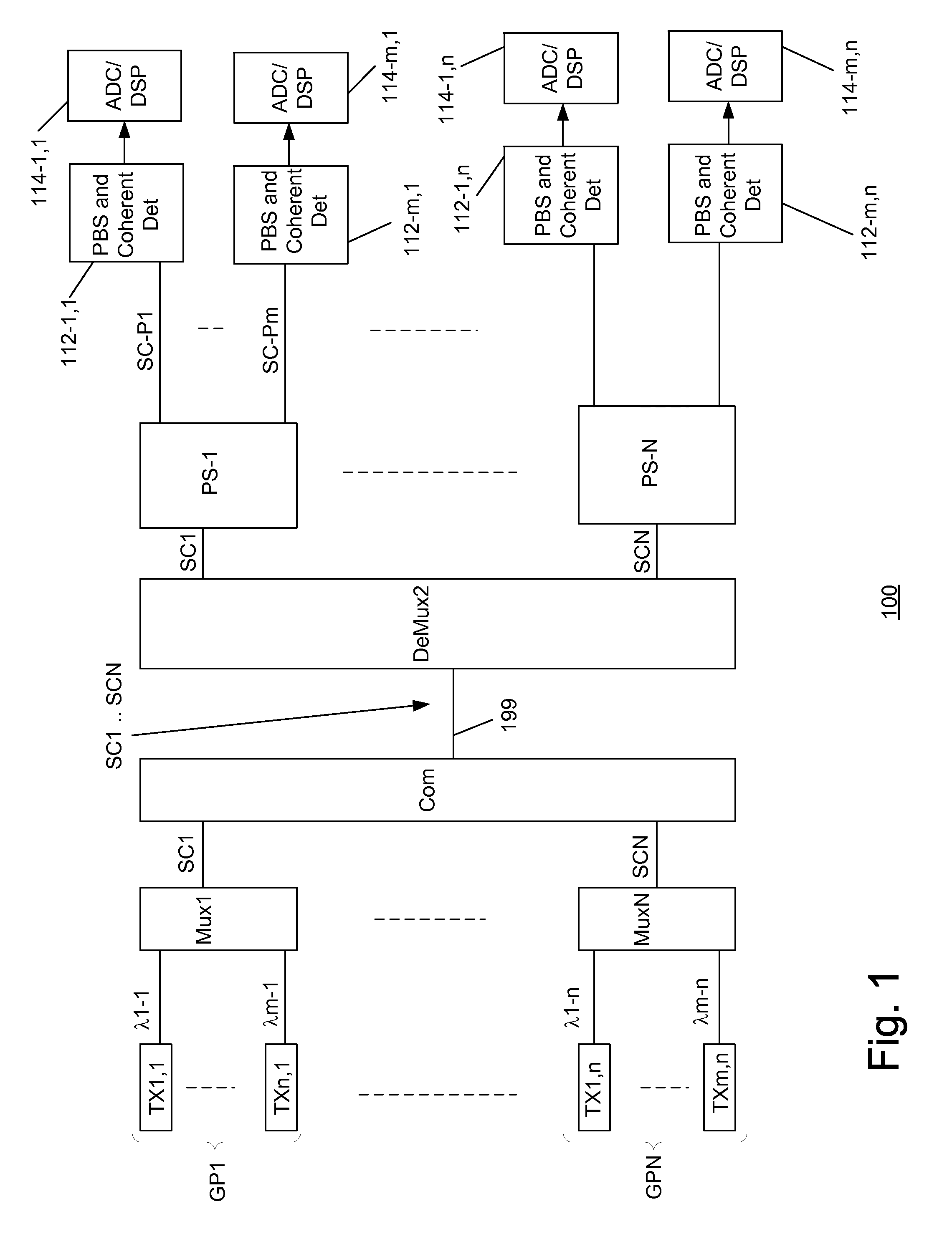
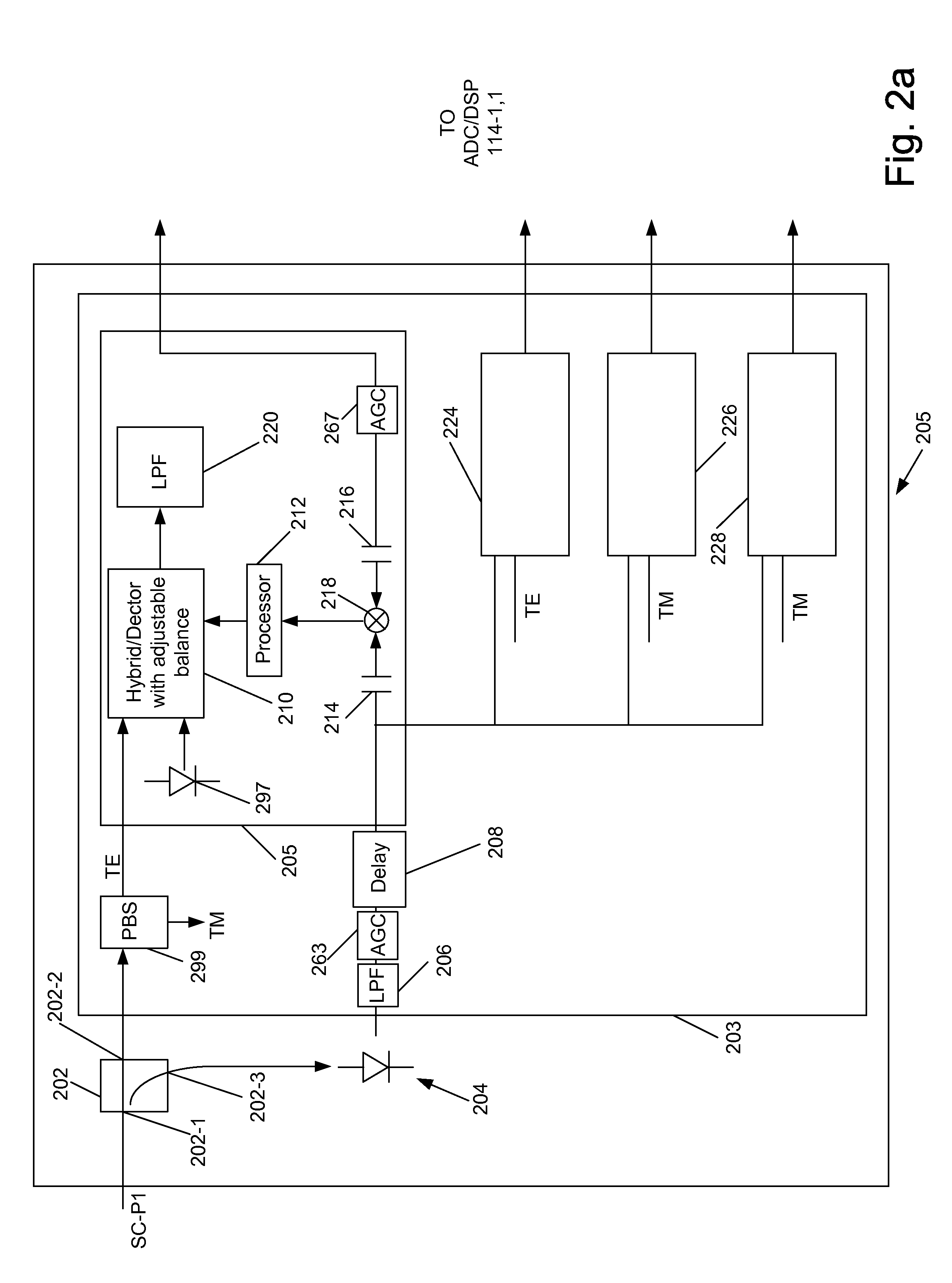
[0025]Consistent with the present disclosure, a coherent detector is provided that includes an optical hybrid that supplies optical signals to a balanced detector. The amount of imbalance or “balance error” (“K” in the above formula) in a balanced detector is identified by determining a difference between an output the balanced detector and an output of a photodiode that receives a portion of an input optical signal provided to the optical hybrid. Based on the balance error, electrical signals generated by the balanced detector or the power of optical signals passing through (or output from) the optical hybrid circuit can be adjusted so that the balance error is minimized or reduced to zero. At this point, imbalance in the balanced detector is corrected so that components of the generated photodiode currents associated with noise in the local oscillator light, as well as the non-selected optical signals in the superchannel, are cancelled out.

[0026]Reference will now be made in detai...


PUM


Abstract

Consistent with the present disclosure, a coherent detector is provided that includes an optical hybrid that supplies optical signals including local oscillator light to a balanced detector. The amount of imbalance or “balance error” in the balanced detector is identified by comparing an output of the balanced detector and an output of a photodiode that receives a portion of an input optical signal provided to the optical hybrid. Based on the balance error, electrical signals generated by the balanced detector or the power of optical signals passing through (or output from) the optical hybrid circuit can be adjusted so that the balance error is minimized or reduced to zero. As a result, imbalance associated with the balanced detector is corrected so that unwanted currents and / or related electrical signals are cancelled out or substantially cancelled out. Such unwanted currents and / or related electrical signals are generated in response to noise in the local oscillator light as well as intensity noise associated with non-selected optical signals in a superchannel.

Description

BACKGROUND[0001]Optical communication systems are known in which optical signals carrying data are transmitted from a first node to a second or receive node over an optical fiber. Often the optical signals, each having a corresponding wavelength, are combined onto an optical fiber to provide a wavelength division multiplexed (WDM) optical signal. At the receive node, the optical signals in the WDM optical signal are optically demultiplexed and converted into corresponding electrical signals, which are then further processed.[0002]Recently, optical communication systems have been deployed in which so-called “superchannels” are transmitted. Each superchannel includes a plurality of optical signals or a group of channels that are relatively close to one another in wavelength. Multiple superchannels can be transmitted and combined onto an optical fiber, and each superchannel may be routed or directed through the optical communication system as an individual channel or optical signal. At...

Claims


Application Information

Patent Timeline
IPC IPC(8): H04J14/02
CPCH04B10/61H04J14/06H04J14/02
Inventor MCNICOL, JOHN D.
Owner INFINERA CORP
Learn More